Written by Pat Tritle Build it
As seen in the Fall 2020 issue of Park Pilot
Download free plans!

Full-size plans Click here for full plans - Sheet 1 🏛️
Tiled plans Click here for tiled plans - Sheet 1 🏛️
Specifications:
Wingspan: 21 inches
Length: 20 inches
Wing area: 139 square inches
Flying weight (with rubber): 59.6 grams
Materials:
Wood:
(1) 1/16 x 3 x 6-inch sheet balsa
(1) 3/32 x 3 x 12-inch sheet balsa
(1) 1/8 x 3 x 12-inch sheet balsa
(4) 1/16 square x 36-inch balsa
(2) 1/16 x 1/8 x 36-inch balsa
(7) 3/32 square x 36-inch balsa
(1) 3/32 x 1/8 x 12-inch balsa
(1) 1/2 x 1-1/2 x 2-inch balsa block
Metal:
(1) .020 diameter x 3-inch steel wire
(1) .032 diameter x 12-inch steel wire
(1) .015 x 3/16 x 1-inch brass
5/32 OD x 1-1/2-inch aluminum tube
(1) 1/2-inch square of aluminum (from a beverage can)
Miscellaneous:
(1) .004 x 3 x 12 acetate
(1) 7-inch Peck-Polymers propeller
(1) 19-inch single loop of 3/16 Tan rubber
>>I am a big fan of biplanes, but in the FF (Free Flight) realm, setting up a conventional biplane can be a challenge. Because I wanted to do a simple FF biplane without the typical complexity of a conventional setup, I decided to go with a cabin-type fuselage with I-style interplane struts to make the setup nearly foolproof. The result is a fun little sport FF model that is easy to build and will fly well, even in small venues.
The Dosalas is of the conventional stick-and-tissue style of construction, covered with tissue and dope. The lines are straightforward, so not only is the model easy to build, it is also easy to cover for those who have less experience with old-school covering methods.
One unique feature of the Dosalas is its universally adjustable nose block. The setup allows for any combination of side or downthrust that will allow even minute trim adjustments to be made quickly and easily.
The adjustable nose block requires fabricating a couple of metal parts, but the parts can be made easily using simple hand tools. With that, the only thing left is to build a model.
Building the Dosalas: Patterns, wood sizes, and quantities are provided for each of the shaped parts, which are cut from 1/16, 3/32, or 1/8-inch balsa. The nose block is cut from 1/2-inch balsa.

All of the shaped parts are cut from the appropriate-size balsa using the patterns provided in the plans.

The main landing gear and tail skid are bent to shape from steel wire. The main gear is then sandwiched between the balsa mount plates.

The vertical stabilizer is built up from 3/32-inch square balsa. Pat Tritle opted for the swept tail on his prototype.

The horizontal stabilizer is built up directly over the plans using 3/32-inch square balsa.

The top and bottom wings are identical and are built over the same plans. The outer panels are framed first then will be joined to the wing center section.

The wing center section is built up and joined with the outer panels. The wingtips are propped up to the correct dihedral angle using foam blocks while the panels are glued in place.
Building the vertical and horizontal stabilizers: The vertical and horizontal stabilizers are built directly over the construction drawings. The model was laid out with either a straight or swept vertical tail, so decide which one you prefer and build it accordingly. Construction is entirely from 3/32-inch square balsa. With the frames completed, lift the assemblies from the board and sand to shape.
Building the wings: Both wings are identical and are built directly over the plans. Begin by pinning the 1/16-inch square balsa bottom spars in place over the plans. Fit and glue ribs R2 to R5 in place on the spars followed by the 1/16 x 1/8-inch balsa TE (trailing edge) and 1/8-inch balsa LE (leading edge).
When dry, remove the wing panels from the board. Place a 11/16-inch block under each W5 rib and pin the panels back in place. Fit the 1/16-inch square balsa bottom spar in place followed by the W1 ribs, the LEs, and the TEs, and glue in place.
Fit and glue the 1/16-inch square balsa top spars in place to complete the assembly. When dry, remove the wing assembly from the board and sand to the final shape then build a second wing in the same fashion.
Building the fuselage: Begin by pinning BWS, MPM, and the 3/32 x 1/8-inch balsa top wing saddle in place over the plans. Add the remaining 3/32-inch square balsa longerons and vertical and diagonal bracing. Fit the 1/16-inch balsa fill at the front end, flush with the board. Build the second side frame, but on this one, the front sheeting will be flush with the top edge.
To join the frames, cut the four 3/32-inch balsa crosspieces and pin two of them in place over the fuselage assembly top view drawing. Pin the side frames in place upside down over the drawing, align, and glue in place, followed by the bottom crosspieces at the front and back of part BWS. Pull the tail post together and glue.
Remove the assembly from the board and fit the crosspieces in place in the rear of the fuselage. Fit and glue formers 1, 2, and 3 in place, along with the bottom crosspieces.
Bend the main gear to shape from .032-inch steel wire using the provided pattern, sandwich it between the 1/16-inch balsa landing gear mount plates as shown, and glue it in place. Bend the tail skid from .020-inch steel wire and fit it into the tail post, but don’t glue it in place until after the fuselage is covered.
Building the nose block: The nose block was cut to basic shape and NB1 and NB2 were aligned and glued together. The holes were drilled as shown on the plans then the block was carved and sanded to final shape.
The nose bushing was cut from an aluminum beverage can and fitted onto the block. The adjustment link was made from .015-inch thick brass drilled at the top then the slot was cut into the bottom using a Dremel cutoff wheel.
The propeller hook was bent from .032-inch steel wire and all of the parts were dry-fitted together. The propeller won’t be permanently fitted until the nose block has been sealed and painted.

The wings and tail section parts are all assembled, sanded to shape, and ready for covering.

The fuselage side frames are built directly over the plans. Both are identical until the sheeting is fitted into the forward bay. The sheeting will be fitted flush with the outside edge of each side frame.

The side frames are joined upside down directly over the fuselage top view. The frames are aligned vertically and the top and bottom cabin crosspieces are then added.
Covering: Before covering begins, give the entire airframe a detail sanding to remove any irregularities on the parts. Dry-fit all of the major components to ensure proper fit and alignment. With that done, give all of the frames three or four coats of nitrate dope with a light sanding between each to remove the “balsa fuzz” from the frames.
Domestic tissue was used to cover the wings and tail and had to be applied dry. The tissue was cut to size and glued in place by wicking thinner through the cover. After it was attached, a coat of thinned nitrate dope was applied to the edges to seal the covering in place.
Japanese tissue was used on the fuselage, which was also applied dry using the same methods. When dry, the edges were lightly sanded with 220-grit sandpaper to remove any excess tissue around the perimeter.
After all of the frames were covered, they were sprayed with water using an airbrush to shrink the tissue. The wings and tailplanes were pinned to the board using shims until the tissue was dry. The frames were then given a coat of thinned nitrate dope, again pinning the flying surfaces to the board to prevent warping. When dry, the trim was cut from Japanese tissue and doped in place, followed by two additional coats of thinned nitrate dope.
Final assembly: Cut the windows from .004-inch thick acetate. Plastic page protectors also work well for making the windows on models such as the Dosalas. Fit and glue the tail skid in place then align and glue the bottom wing onto the fuselage.
Using the wing for alignment reference, glue the vertical and horizontal stabilizers in place, followed by the top wing. The interplane struts are then aligned and glued in place as shown in the wing assembly and front view assembly drawings. Mount the wheels to complete the model.
With the nose block assembly sealed and painted, reassemble the propeller and propeller hook and secure the propeller. The finished model flew with approximately 8° downthrust and 1.5° right thrust. Secure the adjustment link with a #2 sheet metal screw. Make up a 19-inch double loop of 1/8-inch tan rubber and install it using the 5/52-inch OD (outside diameter) aluminum tube motor peg.
Wind in a couple hundred turns and allow the motor to unwind and take a natural set in the fuselage. Balance the model 25/16 inches from the LE at the root on the top wing as shown.

All of the remaining formers and crosspieces have been added to complete the basic fuselage assembly.

The holes are drilled in the adjustable nose block. The 1/16-inch diameter hole is drilled from the front first, followed by the larger hole from the back. The drill bit was marked to prevent accidentally drilling clear through the block.

The nose block is carved to rough shape then fitted onto the fuselage for final shaping and finish sanding.

The front bearing plate is made from soft aluminum. A small glass bead is then used for the propeller thrust bearing.

The adjustment link is made from brass and held in place with a #2 sheet metal screw. A birch plywood disc is used to ensure a good, solid mount for the adjustment link.
Trimming and flying: Pick a nice, calm day to do the trim flights. Begin with a couple of test glides and adjust the CG (center of gravity) as needed to get a good glide. With an acceptable glide achieved, wind in roughly 400 turns and launch the model.
My aircraft turns naturally to the left with power, but if yours wants to turn right, don’t fight it. Trimming is much easier when you let the model fly the way it wants to.
Launch the airplane slightly nose up. If the model heads right for the ground, reduce the downthrust a bit. If it tends to porpoise, add more downthrust. The right thrust can also be adjusted to help control the size of the circle. As the minor adjustments are made, increase the winds up to roughly 1,000 turns, making any necessary adjustments. When trimmed, the model should deliver flights in the 30 to 40-second range with 1,000 turns in the rubber.
As a side note, because my model turns left, I find it best to launch slightly nose up with the breeze coming from the left at approximately 45°. That way, when the model starts its turn, it will be pointing straight into the breeze and immediately begin to gain altitude. Every model is different, so experiment and see what works best with yours. But one thing is certain: The Dosalas will provide some great flying on calm summer days.


With all of the framing done, the parts are dry-fitted to check for proper fit and alignment. When all is well, disassemble the model and prep it for covering.

All of the major components have been detail sanded and four coats of nitrate dope have been applied in preparation for the tissue covering.

The Dosalas is complete and nearly ready to fly. The only thing left to do is to install the rubber motor and set up the CG and the model will be ready for trim flights.

All of the frames are covered and water-sized, and a coat of nitrate dope has been applied. Shims, pins, and weights are used to prevent warping while the water and dope dry on the more delicate components.

The side windows and windshield are cut from thin acetate. The side windows are glued in place with ZAP Canopy Glue and, when dry, the windshield will be glued in place.


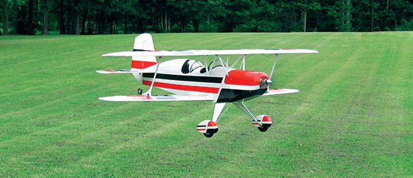
The Dosalas is a perfect setup for smaller flying venues. The aircraft flies nicely in a shallow climb and makes a left circle under power. When the peak altitude is reached, it will gently descend and touch down just as the rubber has completely unwound.
by Pat Tritle | Photos by Pat Tritle | [email protected]