

By Dave Lockhart. Sport & Aerobatics Column. As seen in the Fall 2016 issue of Park Pilot.
For park pilots who gravitate toward aerobatics, there is a plethora of park-size aerobats available on the market. Ranging from 1-ounce ultra micro models to 2-pound foam or balsa construction models, there is a variety of options and aerobatic capabilities. There are a couple of setup techniques that can be applied to virtually all of them—whether built from a kit or ready to fly out of the box.
Sealing the hinge lines of any model can improve its performance in several ways. Preventing the air from leaking through the hinge line reduces drag and increases the effectiveness of the control surfaces. Hinge lines are rarely exactly symmetrical left to right (in the case of left vs. right ailerons or elevators). Sealing the hinge lines prohibits differential air leakage, which can cause unwanted rolling with elevator input or yaw with aileron input. Many of today’s foam models employ a “live” hinge, where the hinge line areas (of the ailerons, elevator, and rudder) are part of the manufacturing process. The hinge line is either thinly molded or machined (post molding) to a thin section so that it is flexible. A manufactured hinge might or might not seal the full distance of the hinge line. In the case of some Depron and EPP foam kits that are constructed by a pilot, the control surfaces are attached using a thin bead of flexible glue, such as Beacon Foam-Tac (foam-tac.com), Welders adhesive (homaxproducts.com), or 3M Blenderm tape (3m.com). The popular ParkZone T-28 (parkzone.com) is an example of an airplane that has manufactured hinges. The stabilizer, elevator, fin, and rudder are thermos-molded foam with a couple of hinged sections on each piece, leaving substantial areas through which leakage can occur. The T-28 ailerons are molded as part of the wing and the hinge line areas are thin, but full wingspan, preventing any air leakage.
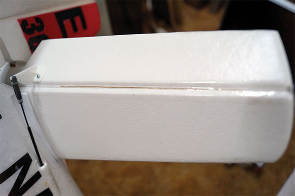
The ParkZone T-28 uses a molded stabilizer and elevator assembly with integrated hinges at the root and tip, leaving an unsealed gap between the hinges.
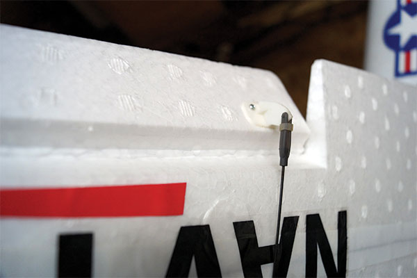
The ParkZone T-28 uses a molded wing and aileron assembly with a smooth top skin that acts as a hinge, while the bottom side is beveled to allow adequate control surface movement.
Most airplanes constructed from balsa—whether from a kit, ARF (Almost Ready to Fly), RTF (Ready to Fly), or BNF (Bind-N-Fly)—do not have sealed hinge lines. The most popular method for sealing hinge lines is the use of tape. Many pilots prefer 3M Blenderm tape, which adheres well to a variety of coverings and foam types. It is also lightweight and flexible, making it effective at sealing a hinge line without compromising the motion of the control surface. For airplanes covered with film such as UltraCote, MonoKote, etc., thin strips of matching covering can be used to seal the hinge lines. The benefit of using covering is that the exact colors can be matched.
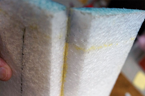
A Fancy Foam Extra 330 has a prebeveled control surface that needs to be hinged. A thin bead of flexible glue is used to attach the control surfaces and act as a live hinge. A couple of small strips of Blenderm tape reinforce the hinge line.
Functionally, hinge line sealing can be done on either the top or bottom surfaces, and only one side needs to be sealed to gain the full benefits. Aesthetically, sealing on the bottom side is preferred because any wrinkles in the tape or covering are less noticeable. On smaller surfaces, it is possible to use a single piece of sealing material for the entire length of the hinge line, but on larger surfaces, using multiple shorter pieces is easier. The process or technique for applying hinge seals is simple, but it takes practice to perfect. The control surface is moved to full deflection (full up for the elevator), and the sealing material is placed on one side of the hinge line bevel. Using light pressure for tape or low heat for iron-on covering, the sealing material is attached for the full length on one edge, then incrementally toward the hinge line, and then onto the opposite bevel. Avoiding wrinkles is important because they can cause the control surfaces to bind at large deflections. A thin ruler with a rounded edge or a Popsicle stick is an effective tool to help work the material into the hinge line.
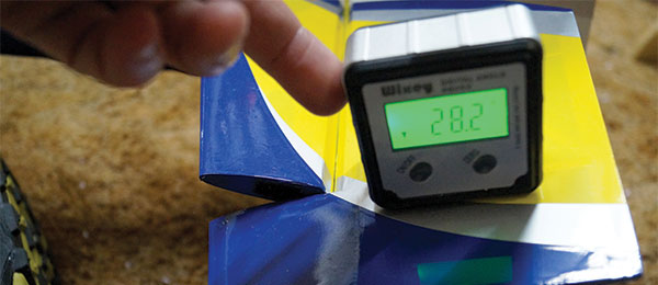
To achieve the best aerobatic performance, it is important to have the proper control-surface deflection. In most cases, ailerons should have equal up- and down-control throw. Rudder throw should be slightly greater to the left, and down-elevator should be slightly more than up-elevator. The extra left rudder throw is essentially used to counter the right thrust of the motor, which is used to offset the effects of torque, P-factor, spiral airflow, and gyroscopic precession. These are all products of a spinning propeller and a long discussion in itself. The extra down-elevator counters the effects of gravity, which in normal flight is accounted for with a small bit of up-elevator trim. In the case of many RTF and BNF models, the servos and control linkages are preinstalled and set for the recommended control throws. For kits and ARFs, the instructions often recommend control throws. It is important to understand that preset control throws are only accurate to a certain degree, and programming dual-rate percentages and exponential percentages in the transmitter do not ensure that the control surfaces are actually moving the desired and equal amounts. Small differences in servos, control linkages, and hinge lines can result in variations in actual control-surface deflection. Measuring the movement of the control surface(s) is the best way to determine the true amount of movement. Given the starting point of an aircraft that is trimmed for straight-and-level flight, it is preferable that the electronic trims on the radio are minimized, and any subtrims (neutral trims) in the radio are close to zero. Minimizing electronic and subtrims can be accomplished by changing the length of the control linkages, tightening or loosening clevises, and making sure enough threads remain in the clevises to maintain the integrity of the linkages. Servos typically can only rotate 45° in each direction from center, and if substantial amounts of rotation are used for trim, it reduces the amount of rotation that can be used for actual deflection for aerobatic maneuvers. As shown in the pictures, there are numerous ways to measure control-surface deflection. With relatively moderate control throws—less than 30° each way—rulers, mechanical throw meters, laser-pointer-type throw meters, and digital throw meters are all viable ways to measure control-surface deflection. Throw set at 30° is more than enough for loops, rolls, stall turns, spins, etc.
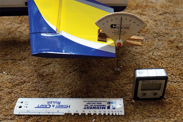
A variety of tools such as a ruler, throw meters, digital angle meters, etc., can be used to accurately measure control surface throw.
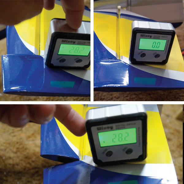
Digital meters or laser pointers can accurately measure control throw to tenths of a degree.
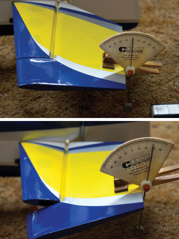
Many commercially available throw meters assist in making quick and accurate readings of control surface throws.
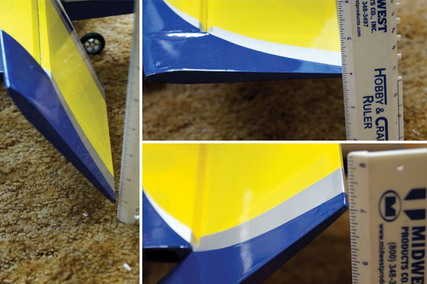
At large control surface deflections (greater than 45°), some meter calibration range is exceeded, but a simple ruler never fails.
Depending on the aircraft, most post-stall 3-D maneuvers—harriers, walls, parachutes, etc.—will benefit from more than 30° of control throw on the aileron, elevator, and rudder. Extreme aerobatic tumbling (pop-tops, crankshafts, blenders, etc.) will benefit from more than 60° of control throw on the elevator. Most purpose-made control surface meters are not calibrated to measure more than 30° or 45° of throw, but an old-fashioned ruler works, and any number of digital angle meters, including cellphone apps, work well. With properly sealed control surfaces and accurately set control throws, virtually all aerobatic aircraft will perform more accurately—reducing pilot workload and making all maneuvers easy to accomplish. Knowing the exact control surface deflection also makes it easier to evaluate changes in a setup and replicate a good setup for another aircraft.
Article:


