By Bob Hunt and Dick Sarpolus
As seen in the Spring 2008 issue of Park Pilot.
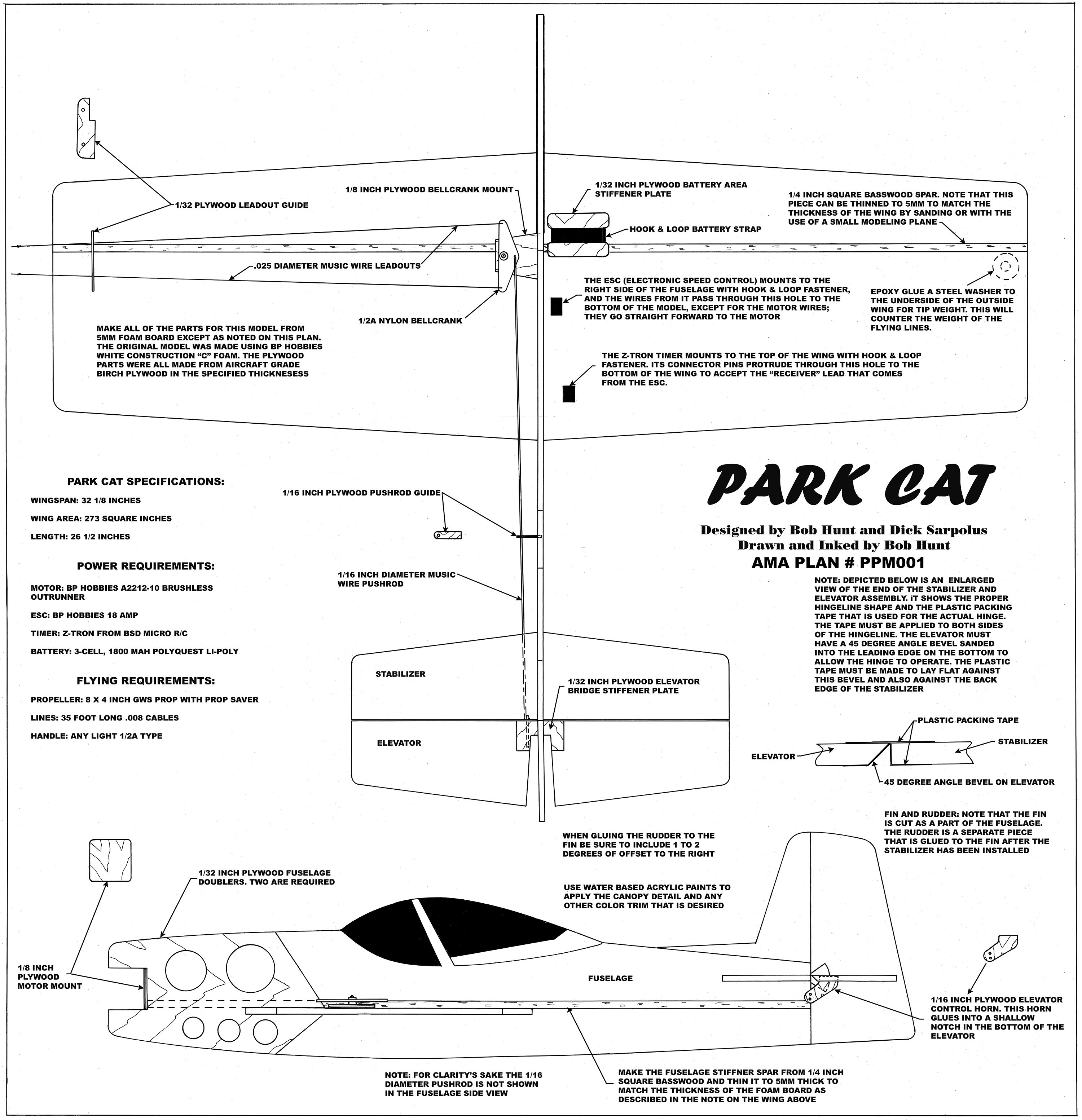
My good friend, Dick Sarpolus, and I joined forces in the design of a very simple-to-construct, all-sheet foam model that we call the Park Cat. Full-size plans are available as a free download at the end of the article.


The basic material used here is 5mm-thick white construction “C” foam that we purchased from BP Hobbies. You can also use Midwest Products Cellfoam 88. For the wing and tail components, you can simply measure out the dimension of the wing and tail pieces onto the foam then carefully slice them out using a straightedge and a hobby knife fitted with a new #11 blade.
To lay the fuselage out, position the plans over a piece of the foam, and wherever there is a curved line, use a pin to punch holes through the plans and into the foam at approximately1/4- to 3/8-inch intervals. For straight line areas on the fuselage, you can just make pin holes through the plans at the beginning and end of each line. Remove the plans then use a pencil to connect the dots and draw the outlines. Cut the fuselage out with the #11 blade and use the straightedge when cutting the straight lines.
There are a few simple-to-make plywood parts needed for this model. These include the fuselage nose doublers, an elevator reinforcement piece, a bellcrank mount, an elevator control horn, a leadout guide, a pushrod guide, a battery area stiffener plate, and a motor mount plate. The plans indicates the thickness of the plywood you should use for each of these parts.
You will also need two 36-inch-long pieces of 1/4-inch square basswood. One of these pieces will become the wing spar, and the other a fuselage spar onto which the top and bottom fuselage halves will be glued. Note that these basswood pieces are just slightly thicker than the 5mm foam pieces that they will be glued to. You can use a sanding block fitted with #220-grit sandpaper to thin down the bass wood strips in the appropriate areas to match the thickness of the foam, or if you have access to a small modeler’s table saw, you can cut 5mm by 1/4-inch pieces of basswood to begin with.
When all of the wood and foam parts are cut out and sanded, and all of the hardware items are in hand (see the plans for a complete list of these), assembling the Park Cat can begin.
Assembly: All the Park Cat parts can be assembled with 5-minute or 15-minute epoxy. Start with the wing. Cut the wing spar to length and lay it down over a piece of waxed paper on a flat building board. Apply a thin coat of epoxy to the edges of the forward and aft sections of the left wing that will butt up against the basswood spar. Make sure that the ends of the foam pieces are flush with the end of the spar. Press the foam pieces firmly against the spar then weight the assembly down flat until the epoxy cures. Repeat this process to glue the other two wing pieces to the spar, being careful to also glue the center joint of the wing halves.


(ABOVE TWO IMAGES) The wing assembly begins by epoxy-gluing the foam wing pieces to the basswood spar. For all gluing operations, Bob Hunt and Dick Sarpolus recommend 15-minute epoxy, although the 5-minute variety will do fine if you are experienced and quick. Weights are used to keep the components flat against the table until the epoxy cures. Be sure to apply epoxy on the ends of the foam that butt together at the center.
Next, glue the upper and lower foam fuselage pieces to the basswood fuselage spar in the same manner as you did the wing. Before you can glue the 1/32-inch plywood doublers—or any of the plywood pieces to the foam—you will have to make small punctures through the smooth skin of the foam. These punctures allow the glue to penetrate the foam and improve grip.

It’s good practice to puncture foam with an awl wherever plywood parts will be glued to the foam. The image shows where the fuselage doubler will be attached. Note that no punctures have been made in the areas of the doubler’s lightening holes.
To puncture accurately, position one of the doublers on its corresponding fuselage side and draw around the rear edges with a #2 pencil. Then trace the lightening holes. Using a sharp awl or scribe, punch a number of shallow holes, being careful not to punch holes in areas where the doublers will not cover them when installed. Use an acid brush to coat the inner face of one of the doublers with a film of epoxy and position it on the fuselage side. Weight this assembly and let it cure then repeat the process to glue the other doubler onto the opposite fuselage side.
Use the same technique to make a row of small punctures through the wing skins along each side of the center line joint then slide the wing through the slot in the fuselage. Line it up carefully and epoxy the wing into the fuselage slot.


(ABOVE TWO IMAGES) Position the stabilizer and elevators so that a 1/16-inch gap separates them. With the assembly face up, place a piece of clear plastic packaging tape across the gap and let it run off the end of the assembly. Trim the tape with a knife and repeat the process on the other end to complete the top hinge. Flip the assembly over and fold the elevators over the stabilizer then apply tape to the bottom. The bottom hinge has to follow the 45° angle that has been sanded into the leading edge of the elevators, allowing the elevator to move both upward and down. Hinging takes practice, so keep trying until it’s perfect.
Glue the plywood elevator joiner piece in (don’t forget the punctures) then carve or sand the lower forward edge of the elevator assembly to a 45° angle. Refer to the hinge detail on the plans then hinge the stabilizer to the elevator assembly using clear plastic packaging tape or Du-Bro Park Flyer Hinge Tape. Cut a shallow slot and epoxy the elevator horn in place.
Slide the tail assembly into the slot at the rear of the fuselage, line it up carefully in all axes, then glue it in. Check the alignment often while the glue cures. Now, epoxy the rudder in place with approximately 1/16- to 3/32-inch off set to the right.

The Park Cat’s 1/16-inch-thick plywood control horn has been epoxy-glued into a shallow slot in the bottom of the elevator. Note the 45° angle sanded into the elevator’s leading edge.
Attach the leadouts to the bellcrank, but do not bend the line attachment loops yet. Glue the 1/8-inch plywood bellcrank mount in position. Bend the pushrod from 1/16-inch-diameter music wire and insert the right angle bend at the rear into the elevator horn. Use a small nylon keeper to secure the pushrod to the horn. Slide the 1/32-inch plywood pushrod guide onto the pushrod and let it hang loosely for now. Insert the right angle bend on the front of the pushrod into the bellcrank from below.
Holding the bellcrank over the mount in the neutral position, move the assembly fore and aft until the elevator is also at neutral. Mark the hole position and drill a starter hole for the sheet metal screw that will anchor the bellcrank. Screw the bellcrank to the mount then position the pushrod guide about halfway between the trailing edge of the wing and the leading edge of the tail. Make a small slot in the foam for the guide and epoxy it in place. Glue the leadout guide in position, and now you can finally bend those line attachment loops.


(ABOVE TWO IMAGES) The first photo shows the ESC and Z-Tron Timer, while the second shows the 1,800 mAh LiPo battery. Wiring is routed through the wing, and hook and loop material solidly anchors the battery.
Position the motor mount that came with your motor on the 1/8-inch plywood motor mount plate. Mark and drill small starter holes for the #2 sheet metal screws. Glue the 1/8-inch plywood mount to the front of the fuselage and make sure that there is at least 1° of offset in it before letting it cure.
Complete the model’s assembly by gluing a 1/4-ounce flat washer to the underside of the outside wing for tip weight.

The completed Park Cat airframe is an exercise in simplicity. A plywood stiffener on the outboard wing prevents the weight of the battery from pulling the hook and loop strap through the wing during maneuvers.
Although you could bend up a 1/16-inch-diameter wire landing gear with small, lightweight wheels for flying from smooth surfaces, we generally like to fly this type of model over grass fields where landing gear isn’t practical or needed. Get a friend to give you an easy hand launch, and make smooth deadstick landings on the grass. The airplane will perform better without the drag and weight of the landing gear, and soft grass is easier on an airplane if a crash should occur.
Dress your model up to suit your taste by adding some trim colors using water-based acrylic paints. With the model’s construction behind me, I’m handing the keyboard over to Dick Sarpolus for his comments on powering the Park Cat.
Power System Stuff: The recommended power system consists of a brushless outrunner motor, a LiPo battery, an RC-type ESC, and a timer specially made for Control Line flying. The objective is a system with approximately 150 watts of power for good flying, meaning a motor that will turn an 8 x 4 propeller and draw approximately 15 amps from a three-cell, 11.1-volt battery with a rating of approximately 1,800 to 1,900 mAh to deliver the current for 5- or 6-minute flight times.
Bob and I used a BP Hobbies A2212-10 brushless outrunner motor for our Park Cat, with a BP Hobbies 18-amp ESC, a three-cell 1,800 mAh PolyQuest LiPo battery, an 8 x 4 GWS propeller, an a Z-Tron timer.
We also installed a simple “prop saver” on the motor shaft. A prop saver is a simple device that uses a small, elastic O-ring to retain the propeller, which allows the propeller to move a little if it hits the ground and helps prevent it from breaking on landings. You’ll also need a LiPo battery charger to handle the battery pack. All of these components—or their equivalents from other manufacturers—are available from your local hobby shop, your favorite mail order house, or internet hobby supplier.
These recommended electric power system components require proper care and handling—particularly the battery charging—to ensure reliable performance and safe operation. We urge you to follow the directions that come with the equipment you use and ask a knowledgeable hobbyist if you have any further questions or concerns.
Flying the Park Cat: Check the plans and your model to ensure that the center of gravity is where it’s supposed to be. Move the battery fore or aft in small increments to achieve this position, double-checking as you go. Fly the Park Cat on 35-foot-long .008-diameter multistrand cables and use a 1/2A-type control handle.
Launch the model downwind to keep tension on the lines until some speed is achieved. This model is capable of most of the aerobatics that are in the official AMA pattern, so start with the easy ones, like loops, and progress as you gain confidence.
Enjoy your Park Cat.
https://parkpilot.s3.us-east-2.amazonaws.com/CatCLStunter-Plans_Download.pdf