

Written by Lucas Weakley Incidence Angles New Technology As seen in the Winter 2018 issue of Park Pilot.
While sitting in my stability and controls class at Embry-Riddle Aeronautical University, I was introduced to the concept of incidence angles. In a nutshell, the wing incidence angle is the angle measured between the wing and fuselage centerlines. If the wing is mounted parallel with the fuselage, there is 0° angle of incidence. Any positive angle of incidence would mean that the leading edge of the wing would be tilted up when mounted to the fuselage. This angle can be optimized when designing the aircraft, depending on its application. During cruise flight, all wings need to have some angled attack against the oncoming air to maintain altitude. By mounting the wing at a positive angle of incidence, the fuselage can cruise at an angle parallel with the ground. Some companies, such as Boeing, intentionally mount their aircrafts’ wings with a zero incidence angle, which makes the fuselage pitch up during cruise and gives the passengers inside of the airplane the feeling of constant climbing. Conversely, military aircraft sometimes have a high wing incidence angle (approximately 5°). This allows the fuselage to be pitched down during flight to allow better visibility over the nose. After hearing this, I naturally began to wonder what would happen if I mounted the wing at an incidence angle of, say, 30°. With a little bit more time on my hands in summer 2017, I set out to test this crazy idea. This incidence angle test is only one of the extreme aerospace engineering experiments that I’ve conducted. I designed and built a modular aircraft that I could reconfigure and easily modify for each of the experiments. I affectionately called this airplane Buster. You can watch a video of how I created it on my YouTube channel. In the video, I also explain the idea of incidence angles a bit more with some visuals. Buster was designed to be much bigger and heavier than most of my other airplanes. This was to ensure that its flight performance more accurately represented that of a full-scale aircraft. In the wing incidence angle testing configuration, the airplane had a 70-inch wingspan with four motors mounted to the wing and seven servos among the five control surfaces. I also designed 3D-printed mounts for the wing and the horizontal stabilizer so that I could loosen them and rotate the lifting surfaces to any angle that I wanted. It was a fun challenge to get everything to properly work.
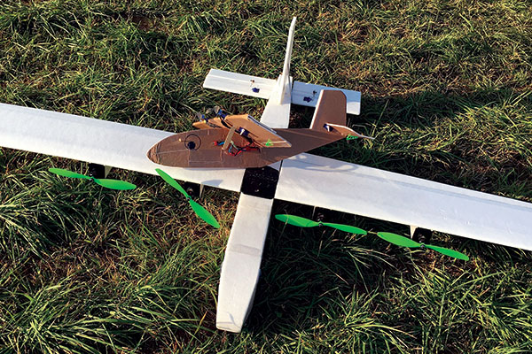
This is a good size comparison between the two models. In this view, the Buster is fitted with an 80-inch wing, so it’s slightly bigger than before.
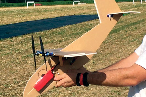
This is a good view of the angle at which the wing was glued onto the fuselage of the baby Buster. The photo was taken before its maiden flight.
Taking the airplane out on its first test flight, I had everything mounted with zero incidence angles so that I could get a feel for the airplane on its first couple of flights. With the wing mounted at a zero incidence angle, the fuselage was noticeably pitched up a few degrees as it flew through level flight. I brought the airplane down and adjusted the wing incidence angle to approximately 2°. When I got the aircraft back up into the air, the fuselage was level with the horizon. It was so exciting to see these principles that I’ve learned in class actually work in the real world—not that I had any doubts! After I landed, it was time for the big test. I set the incidence angle to approximately 30°. This would mean that while the airplane flew, the fuselage would be pitched down at such a severe angle that anyone watching it would think that it was about to crash. I spooled up the four motors, testing the thrust against the weight of the aircraft. Holding the wing parallel with the ground, I pushed the airplane into the air and it swiftly pitched up, looped, and slammed into the ground. In my haste to set up Buster’s wing, I forgot to move the battery forward because the fuselage would have been shortened a lot by the new angle. The CG (center of gravity) was way too far back, making the airplane unstable. That night, I fixed Buster and I brought it back out to the field the next morning. I set the wing to a less-absurd angle of approximately 15° (still much higher than any other airplane that I know of) and I had a friend help me hand-launch the airplane so that I could keep my finger on the elevator stick. This time (with the CG in the right spot), Buster got up into the air, but definitely did not like to fly anymore. The airplane was bucking back and forth as the fuselage tried to become level with the oncoming air and then the wing stalled because it was at too high of an angle of attack. I wasn’t even able to get the airplane to turn before it would tip stall and I would have to recover. In the end, I learned that the fuselage creates so much drag at higher angles of attack that the airplane cannot fly unless the fuselage is also at least close to being in the same flightline as the wing. Although this wasn’t a failure, it was a little bit disappointing. I left the idea there and got ready to set Buster up for another experiment. Later in July 2017, while I was at Flite Fest (flitefest.com) in Malvern, Ohio, I spent some time in one of the build tents fabricating a miniaturized version of Buster with a profile fuselage (to eliminate the drag that plagued the realistic Buster). I vaguely knew what I was trying to build, eyeballing the proportions, and I sketched out fuselage shapes directly onto the foam. I was limited in my parts. I only had right-hand propellers for my twin motors, and the smallest battery I had was a 2,200 mAh three-cell LiPo, which made this little 28-inch wingspan airplane weigh more than 1 pound. Everyone was skeptical of the airplane’s airworthiness, especially with the wing “on crooked,” as many people informed me during its impromptu construction. But I made my way to the flightline and had a friend toss it into the air. Honestly, we were expecting it to nose into the ground because of the absurd wing loading and get a few laughs in while it flew briefly in its comical configuration. I gave it full power, threw it wings level (not fuselage level) to the horizon, and I put in some up-elevator, anticipating the drop. This was the best-flying airplane that I brought to the event! The baby Buster was a little touchy to begin with, but after a few flights and some trim, it was incredibly stable—and fast. Several people came by, wondering what kind of an airplane it was. One person even said, “It hurts my brain to watch your airplane fly.”
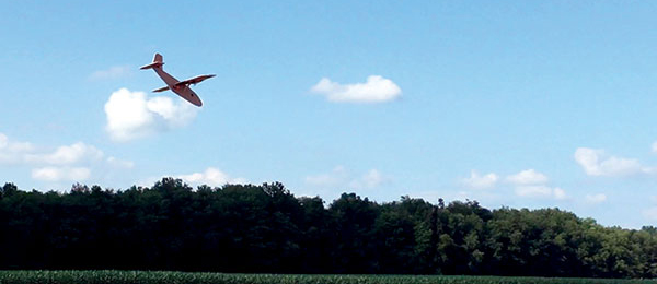
This airplane was fast and very easy to fly! When all trimmed out, the fuselage acted like a big vertical stabilizer.
Explaining the concept of wing incidence angles to curious bystanders was a great experience. Perhaps I inspired them to try something different. If it wasn’t for a couple of brownouts with the receiver, I would still be flying the baby Buster today. Even so, the process of testing these ideas is incredibly fun, and I can’t wait to do more!
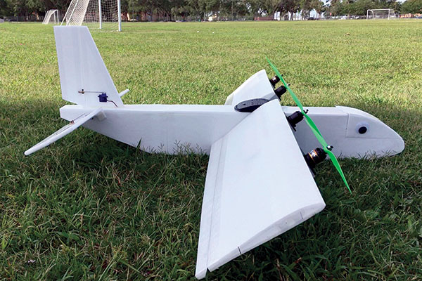
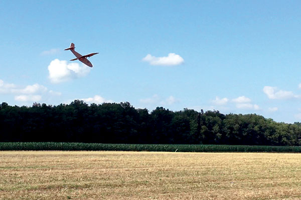
This was how the wing and elevator were mounted for the Buster’s final incidence angle test. It was also the configuration during the crash.
Article:


