

Written by Joe Hass Fly from land or water Product review As seen in the Fall 2017 issue of Park Pilot.
Specifications:
Type: Foam kit Skill level: Intermediate Wingspan: 40 inches Length: 30 inches Weight: 17 to 22 ounces Needed to complete: Spin Max 2212-6 or equivalent brushless motor; 30- to 50-amp ESC; APC 6 x 4E propeller; 1,300 to 2,200 3S LiPo battery; four-channel radio and receiver; and three 9-gram micro servos Price: $79.95 Info: modelaero.comFeatures:
>> An attractive and unusual design >> Includes B-2 decals >> Flies equally well off of grass or waterProduct Review
Scott DeTray, of Model Aero, has come up with a variety of designs that have looked great and performed even better. He has done it again with the Spirit Seaplane. Based on the planform of the B-2 Stealth Bomber, it is equally at home on land or water, indoors or out. It is constructed of foam and carbon fiber with plywood strategically added. You can get the motor, ESC, and servos from Model Aero, too.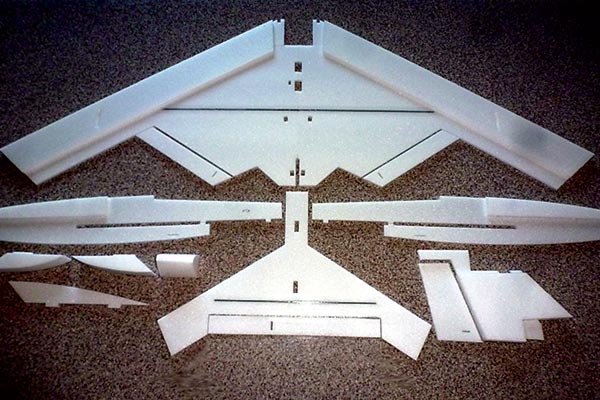
These major assemblies make up the Spirit before final assembly.
Although a single adhesive could be used, this build really benefits from a combination of foam-safe CA, foam-safe spray-on contact cement, Foam-Tac, and epoxy. The Spirit is constructed from laser-cut Model Plane Foam that is similar to Depron, but not as brittle. Construction begins with joining the wing parts together with epoxy or Foam-Tac. The wing is reinforced with strips of carbon fiber glued in with epoxy. These joints are then reinforced with Scotch MultiTask or Transparent tape over the carbon fiber. This creates an I Beam-type structure that helps stiffen the wing. This technique is duplicated on the horizontal stabilizer. The ailerons and elevator are hinged with either Scotch tape or Blenderm surgical tape on the top surface. The instructions detail adding a second strip of tape on the bottom of the hinge to create a more stable and durable hinge line. I used spray-on contact cement to laminate the bottom foam pieces to the wing. Leaving the foam pieces in their carriers while spraying on the contact cement eliminates getting contact cement on the edges of the foam. Simply spray on the adhesive then cut the part out of the carrier. Using 80-grit sandpaper on a block, sand the leading edges to a round shape and square up the tips of the foam surfaces. Move to 200-grit sandpaper to finish the job. The final step for the wing and stabilizer is to apply the included self-adhesive finishing decals. Clean the foam surfaces well with tape or a tack rag. Use some of the scrap foam to keep the wing level while applying the decals. Work on the fuselage begins with laminating the fuselage sides with the battery tray doublers. It is important to first determine how your battery, with its hook-and-loop fastener, fits under the top hatch. My battery needed to be postitioned forward. Consider trimming the top edge of the doublers to allow more room for the battery under the hatch. Again, contact cement is recommended to laminate the doublers to the fuselage sides. Now add the battery tray followed by the two fuselage formers. Make sure that everything is square. I used medium foam-safe CA adhesive with an accelerator. Next, add the fuselage bottom. Although I used Foam-Tac adhesive on this build, I would use 5-minute epoxy in the future, being careful to not apply too much while still making sure there is enough to ensure that the hull is waterproof.
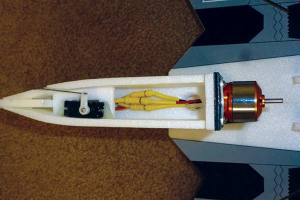
The elevator, motor, and wiring are installed in the motor pylon.
If you are flying from water, now is a great time to consider toughening up the foam on the front bottom. I masked off the sides of the fuselage with 3-inch low-tack tape before I sprayed the bottom with contact cement. I then positioned 3/4-ounce fiberglass cloth on the fuselage bottom, followed by a thorough application of foam-safe CA adhesive. The contact cement allows you to hold the fiberglass in place. The CA makes the fiberglass hard and permanently attaches it to the foam. Use the accelerator judicially. After the CA is hard, sand the hull bottom flush with the fuselage sides. Do not round the edges of the hull. I used 80-grit sandpaper on a block to shape it, followed by 200-grit sandpaper to finish. The fuselage is now attached to the wing using the precut tabs for location. Again, make sure everything is square. I used Foam-Tac for this assembly. Epoxy the plywood pylon reinforcement plate to the wing. The motor pylon includes the elevator servo. Again, use contact cement to laminate the vertical stabilizer and pylon. I used a combination of foam-safe CA glue and epoxy adhesives to attach all of the pieces of the motor nacelle. The plywood motor mount was drilled for the motor before attaching it to the pylon. The elevator servo was epoxied in place in the included foam mount. A slot was cut in the side of the nacelle to allow passage of the elevator pushrod. Sand the leading and trailing edges of the pylon. Trial fit the rudder and CA hinges. I mounted the motor and drilled a small hole in the bottom of the nacelle to allow the motor wires to enter. I installed the motor, motor wires, servo, and servo extensions in the nacelle before I attached the pylon to the wing. Take your time and trial-fit everything. I propped up the wing/fuselage combination on a flat surface then put a straightedge across the top of the nacelle to verify that the pylon and nacelle were level while checking for stabilizer tilt. I then removed the pylon and applied 5-minute epoxy. Push the pieces together and again verify the alignment. After the pylon has cured, configure the elevator pushrod and glue the horizontal stabilizer to the top of the pylon. I didn’t install the top fin until I had completed the aircraft. The aileron and rudder servos are installed in the wing and covered by the fuselage. Epoxy holds them in place. The aileron has a plywood extension screwed to the servo arm to get the proper angle for the ailerons. Assemble and install the aileron pushrods.
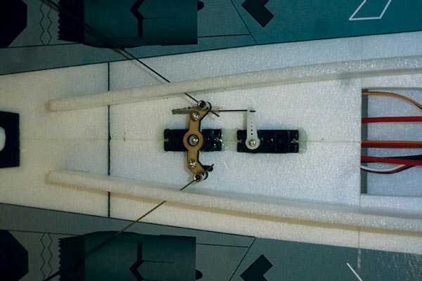
The aileron and rudder servos are installed in the wing and covered by the fuselage.
The rudder pushrod passes through a plastic tube. Make sure the tube is waterproofed as it exits the fuselage. Verify that all of the electronics work before gluing the rear fuselage bottom in place and sanding it to match the fuselage sides. Refer to the instructions and measure the location of the hatch cut lines. Mark those locations on the top of the fuselage. I used epoxy, applying it only to the areas where the fuselage top will be permanently attached. After that cured, I applied the canopy decal. When the decal was set, I marked the location of the hatch lines and cut the foam with a new blade and a straightedge. The instructions call for scrap foam to provide attachment for the hatch. Because of my battery height, I used 1/16-inch plywood instead. I made the cutout for the heat sink and attached the ESC and heat sink to the hatch with 5-minute epoxy. The nose cone and wingtip floats are laminated together with spray-on contact cement. Double-check the width of the nose cone and only use as many pieces as necessary. Sand the wingtip floats to shape. I used 5-minute epoxy to attach all three pieces. Make sure that the nose cone is waterproof at the attachment to the front of the fuselage and sand it to shape. Carefully round the top of the fuselage, making sure to not sand the canopy decal. Attach the top fin. I painted the nose cone with Tamiya flat black brush-on paint. It is foam safe and dries quickly. Because of weather, the Spirit’s first flight was indoors with a 3S 2,200 mAh LiPo battery. It easily handled the artificial turf and lifted off quickly. It flew well and verified the control response, but I could never reach full throttle. At a slower speed, you will need to use a lot of rudder for turns. The Spirit is capable of a full array of typical maneuvers, including loops, rolls, Figure Eights, a Split S, Immelmanns, and inverted flight. Landings were predictable. Even with multiple takeoffs, landings, and maneuvers, I only used 650 mAh of the 2,200 mAh 3S LiPo battery.
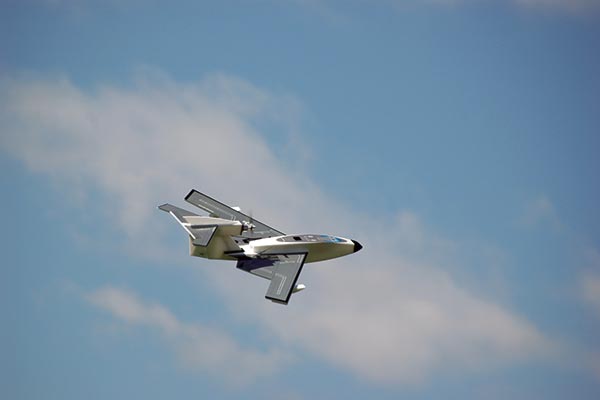
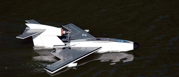
The Spirit presents well at any angle.
Remember that this is not a 3-D aircraft; no bank and yank at full throttle. Coordinated controls and throttle management get you realistic, jetlike performance. It is a blast! Now for water flying! While taking the float photos, I discovered that any application of power caused the left wingtip to dive into the water. I found that placing the battery on the right side of the fuselage, coupled with the smooth application of power, solved that problem. The wind was roughly 10 mph with a moderate chop (especially for the size of the aircraft). I taxied the Spirit into the wind and slowly advanced the throttle, working the ailerons to keep the wings level as the aircraft quickly accelerated and got on step. At roughly half throttle and 20 feet later, a small application of up-elevator got the Spirit airborne. Touch-and-gos are easy. Just point the Spirit into the wind, keep the wings level, and work the throttle. Again, smooth control input is the order of the day. The Spirit presents itself well in the air. It is impressive, performing a full complement of maneuvers. This isn’t a kit for a first-timer, but carefully studying the instructions, including the parts locator and pictures, will get you an aircraft that you will be proud to take to the lake or field. -Joe Hass [email protected]
Article:


