

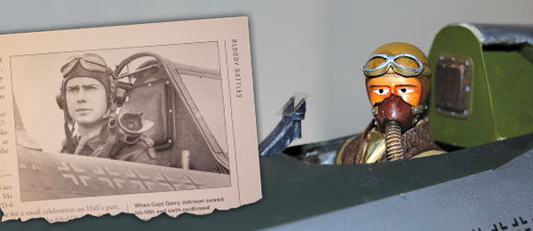
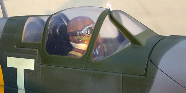
Inspired by this historic photograph, Rob Caso’s modified Williams Bros. pilot bust is ready for business in the P-47’s scratch-built “office.” Article and photos by the author. Featured in the Summer 2008 issue of Park Pilot.
The development of aircraft succeeded that of boats, so nautical terms were often applied to aircraft but with certain generalizations. The etymology of “coxswain” is literally “boat servant,” and refers to the crew member responsible for steering the craft. In the day of cloth sail and wooden boats, the steerage location was often situated partially below the surface of a ship’s deck, resembling a sort of pit, so “cockpit” became the aviation term for the location from which an aircraft is piloted. The two most prominent focal points on any aircraft, model or otherwise, are the engine(s) and cockpit. Unless the aircraft has unusual features like five wings or some particularly prominent marking, an admirer’s eye will most likely to be drawn to the cockpit or engine areas. An engine is usually situated on one extremity or another of an aircraft, often protruding, so it draws attention. The eye-catching element goes for the cockpit, too, but for a different reason The cockpit is where the admirer would be if he or she were piloting the craft, so perhaps it’s the human element that draws the gaze.
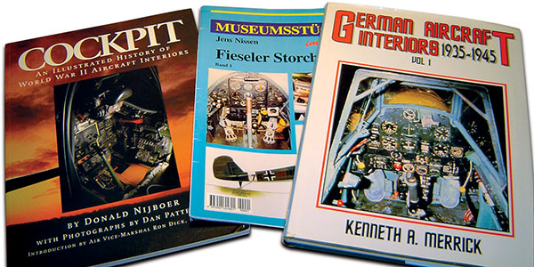
There is no shortage of very good, cockpit-specific references. Even though it’s often overlooked in smaller scales, the level of detail you can create for your models is endless.
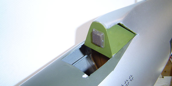
This P-47 begged for greater detail, and the model surely appears unfinished without a proper cockpit. Thunderbolt cockpit detail starts with boxing out the aft section with plastic on a wood frame. Make the headrest base from a piece of sheet plastic, and use balsa sheet to make the cushion.
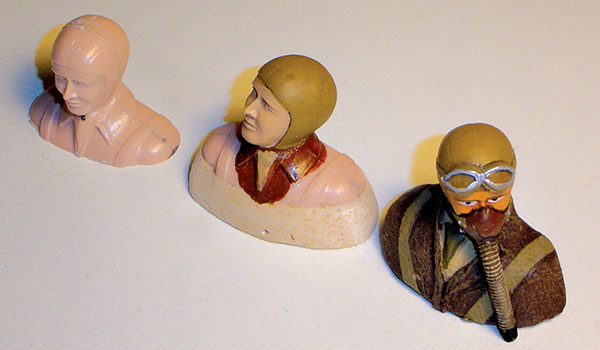
The 1/12-scale Williams Bros. pilot is pretty basic, but it has all the essentials. You can reposition the head to create interest, and pose the head looking slightly up or down by making the cut at an angle.
Keep these things in mind when building and detailing scale models is important. If you already know that people will automatically focus on specific parts of your model, it’s wise to ensure that they are appropriately represented. For me, the scale effect is tainted when I see a nice model performing a flypast with no pilot figure in the cockpit. The model may be perfect to the last detail, but if the pilot is omitted, all is lost. Modeling a pilot and a few cockpit details is not that hard to do. The pilot does not have to be elaborate or even modeled in three dimensions to be convincing. Many of my small electrics carry a painted, wooden profile of a pilot. It’s a super easy way to do the job.
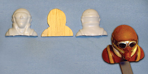
This is a typical, vacuum-formed pilot bust ,ready for detailing. Rob cut an inner profile to which he glued each half. He filled the seam with putty, then painted the bust with plastic model paint. Darker shading helps to accentuate the different colors.
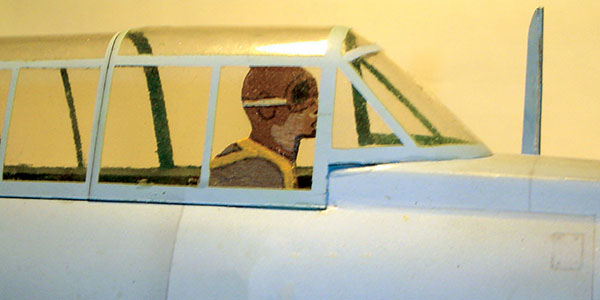
Just one glance and it’s clear to see why the busy cockpit of Rob’s Fiessler Fi-156 Storch creates a lot of visual interest. The cockpit is where the pilot sits, and that’s always the center of attention.
This simplest representation of a pilot, the painted, wooden profile, is made to be viewed from either side view or from front and back, depending upon the layout of the windshield, windscreen or canopy. A profile pilot for a park model weighs next to nothing, and you don’t even have to paint it. Just grab an image off the Internet, size it, cut it out, glue it to a piece of wood and it’s ready to “drive.” When size and weight are not critical issues, a three-dimensional bust (head and shoulders) offers greater realism. I have a few plastic busts made by Williams Bros., and their 1/12-scale pilots seem to fit nicely in most of my small models. Williams Bros. busts come in different styles — World War I, World War II, Sport and Pylon (racing). One front and one rear half of each bust come in each kit, and goggles are also provided where appropriate. Just glue the two parts together and paint the figure for the basic “git ’er done.” There are plenty of tricks to making a Williams Bros. pilot look extremely realistic. The halves will align better if their mating surfaces are trued. Tape a piece of fine sandpaper to the table, then rub the mating surface of each half against it with a back-and-forth motion. Most vacuum-formed pilots go together similarly, but the plastic is usually very thin plastic, so applying glue and aligning the halves can be difficult. Small strips of plastic can be glued to the inside edge of one half as guides to align the opposite half, or the outline of the pilot can be traced onto a thin sheet of balsa. Then you can cut it out and glue each half to the balsa crutch with medium CA.
Simple wood “profile” pilot keeps weight down. Details are painted, then outlined with felt marker.
After joining a plastic figure with liquid plastic model cement or CA, use plastic model filler to fill the seam, and blend it smoothly with needle files or fine sandpaper. Paint and detail for your pilots will be in my next installment. While you’re preparing your pilot, consider how the pilot and cockpit of the full-size aircraft would be equipped. Get some photographs. Don’t spend time modeling things that you’re not going to see, but make the readily visible objects — a head rest, machine gun or control stick — out of plastic or wood. Profile shapes are as good for most of these objects as they are for a pilot – and will look great as your model whizzes by.
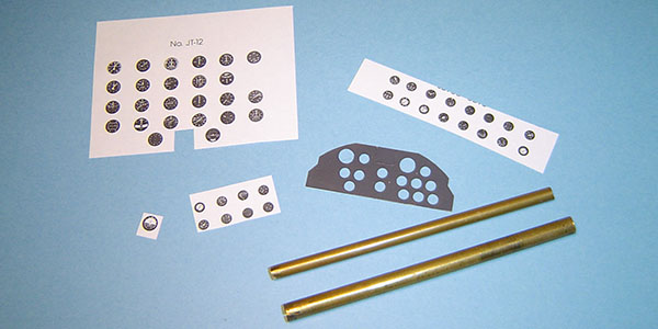
Instrument panels can be constructed from plastic sheet and paper instruments. Sharpen brass tubes to “drill” holes in the panel for the instruments.
My new 31-inch P-47 Thunderbolt needed a decent cockpit to finish it off. Using reference photos, I boxed in the area behind the pilot with plastic sheet, and painted the interior green. Then I added a headrest, an aerial, a rearview mirror and the reflector gun sight. For open cockpit models, I usually fabricate an instrument panel using dials drawn on the computer or by hand. I cut the panel from a plastic sheet, and make holes for the dials with sharpened brass tubing. Paper instruments can be glued behind the holes in the panel, then laminate another sheet over the back for support. Small blobs of epoxy or white glue flowed into the instrument dial cutouts will give the appearance of glass when cured. Add a few switches and other details and you’re done.
Article:


