

Read Time 6 mins
Written by Lucas Weakley Incidence Angles New Technology As seen in the Winter 2018 issue of Park Pilot.
While sitting in my stability and controls class at Embry-Riddle Aeronautical University, I was introduced to the concept of incidence angles. In a nutshell, the wing incidence angle is the angle measured between the wing and fuselage centerlines. If the wing is mounted parallel with the fuselage, there is 0° angle of incidence. Any positive angle of incidence would mean that the leading edge of the wing would be tilted up when mounted to the fuselage. This angle can be optimized when designing the aircraft, depending on its application. During cruise flight, all wings need to have some angled attack against the oncoming air to maintain altitude. By mounting the wing at a positive angle of incidence, the fuselage can cruise at an angle parallel with the ground. Some companies, such as Boeing, intentionally mount their aircrafts’ wings with a zero incidence angle, which makes the fuselage pitch up during cruise and gives the passengers inside of the airplane the feeling of constant climbing. Conversely, military aircraft sometimes have a high wing incidence angle (approximately 5°). This allows the fuselage to be pitched down during flight to allow better visibility over the nose. After hearing this, I naturally began to wonder what would happen if I mounted the wing at an incidence angle of, say, 30°. With a little bit more time on my hands in summer 2017, I set out to test this crazy idea. This incidence angle test is only one of the extreme aerospace engineering experiments that I’ve conducted. I designed and built a modular aircraft that I could reconfigure and easily modify for each of the experiments. I affectionately called this airplane Buster. You can watch a video of how I created it on my YouTube channel. In the video, I also explain the idea of incidence angles a bit more with some visuals. Buster was designed to be much bigger and heavier than most of my other airplanes. This was to ensure that its flight performance more accurately represented that of a full-scale aircraft. In the wing incidence angle testing configuration, the airplane had a 70-inch wingspan with four motors mounted to the wing and seven servos among the five control surfaces. I also designed 3D-printed mounts for the wing and the horizontal stabilizer so that I could loosen them and rotate the lifting surfaces to any angle that I wanted. It was a fun challenge to get everything to properly work.
Taking the airplane out on its first test flight, I had everything mounted with zero incidence angles so that I could get a feel for the airplane on its first couple of flights. With the wing mounted at a zero incidence angle, the fuselage was noticeably pitched up a few degrees as it flew through level flight. I brought the airplane down and adjusted the wing incidence angle to approximately 2°. When I got the aircraft back up into the air, the fuselage was level with the horizon. It was so exciting to see these principles that I’ve learned in class actually work in the real world—not that I had any doubts! After I landed, it was time for the big test. I set the incidence angle to approximately 30°. This would mean that while the airplane flew, the fuselage would be pitched down at such a severe angle that anyone watching it would think that it was about to crash. I spooled up the four motors, testing the thrust against the weight of the aircraft. Holding the wing parallel with the ground, I pushed the airplane into the air and it swiftly pitched up, looped, and slammed into the ground. In my haste to set up Buster’s wing, I forgot to move the battery forward because the fuselage would have been shortened a lot by the new angle. The CG (center of gravity) was way too far back, making the airplane unstable. That night, I fixed Buster and I brought it back out to the field the next morning. I set the wing to a less-absurd angle of approximately 15° (still much higher than any other airplane that I know of) and I had a friend help me hand-launch the airplane so that I could keep my finger on the elevator stick. This time (with the CG in the right spot), Buster got up into the air, but definitely did not like to fly anymore. The airplane was bucking back and forth as the fuselage tried to become level with the oncoming air and then the wing stalled because it was at too high of an angle of attack. I wasn’t even able to get the airplane to turn before it would tip stall and I would have to recover. In the end, I learned that the fuselage creates so much drag at higher angles of attack that the airplane cannot fly unless the fuselage is also at least close to being in the same flightline as the wing. Although this wasn’t a failure, it was a little bit disappointing. I left the idea there and got ready to set Buster up for another experiment. Later in July 2017, while I was at Flite Fest (flitefest.com) in Malvern, Ohio, I spent some time in one of the build tents fabricating a miniaturized version of Buster with a profile fuselage (to eliminate the drag that plagued the realistic Buster). I vaguely knew what I was trying to build, eyeballing the proportions, and I sketched out fuselage shapes directly onto the foam. I was limited in my parts. I only had right-hand propellers for my twin motors, and the smallest battery I had was a 2,200 mAh three-cell LiPo, which made this little 28-inch wingspan airplane weigh more than 1 pound. Everyone was skeptical of the airplane’s airworthiness, especially with the wing “on crooked,” as many people informed me during its impromptu construction. But I made my way to the flightline and had a friend toss it into the air. Honestly, we were expecting it to nose into the ground because of the absurd wing loading and get a few laughs in while it flew briefly in its comical configuration. I gave it full power, threw it wings level (not fuselage level) to the horizon, and I put in some up-elevator, anticipating the drop. This was the best-flying airplane that I brought to the event! The baby Buster was a little touchy to begin with, but after a few flights and some trim, it was incredibly stable—and fast. Several people came by, wondering what kind of an airplane it was. One person even said, “It hurts my brain to watch your airplane fly.”
Explaining the concept of wing incidence angles to curious bystanders was a great experience. Perhaps I inspired them to try something different. If it wasn’t for a couple of brownouts with the receiver, I would still be flying the baby Buster today. Even so, the process of testing these ideas is incredibly fun, and I can’t wait to do more!
Written by Lucas Weakley Incidence Angles New Technology As seen in the Winter 2018 issue of Park Pilot.
While sitting in my stability and controls class at Embry-Riddle Aeronautical University, I was introduced to the concept of incidence angles. In a nutshell, the wing incidence angle is the angle measured between the wing and fuselage centerlines. If the wing is mounted parallel with the fuselage, there is 0° angle of incidence. Any positive angle of incidence would mean that the leading edge of the wing would be tilted up when mounted to the fuselage. This angle can be optimized when designing the aircraft, depending on its application. During cruise flight, all wings need to have some angled attack against the oncoming air to maintain altitude. By mounting the wing at a positive angle of incidence, the fuselage can cruise at an angle parallel with the ground. Some companies, such as Boeing, intentionally mount their aircrafts’ wings with a zero incidence angle, which makes the fuselage pitch up during cruise and gives the passengers inside of the airplane the feeling of constant climbing. Conversely, military aircraft sometimes have a high wing incidence angle (approximately 5°). This allows the fuselage to be pitched down during flight to allow better visibility over the nose. After hearing this, I naturally began to wonder what would happen if I mounted the wing at an incidence angle of, say, 30°. With a little bit more time on my hands in summer 2017, I set out to test this crazy idea. This incidence angle test is only one of the extreme aerospace engineering experiments that I’ve conducted. I designed and built a modular aircraft that I could reconfigure and easily modify for each of the experiments. I affectionately called this airplane Buster. You can watch a video of how I created it on my YouTube channel. In the video, I also explain the idea of incidence angles a bit more with some visuals. Buster was designed to be much bigger and heavier than most of my other airplanes. This was to ensure that its flight performance more accurately represented that of a full-scale aircraft. In the wing incidence angle testing configuration, the airplane had a 70-inch wingspan with four motors mounted to the wing and seven servos among the five control surfaces. I also designed 3D-printed mounts for the wing and the horizontal stabilizer so that I could loosen them and rotate the lifting surfaces to any angle that I wanted. It was a fun challenge to get everything to properly work.
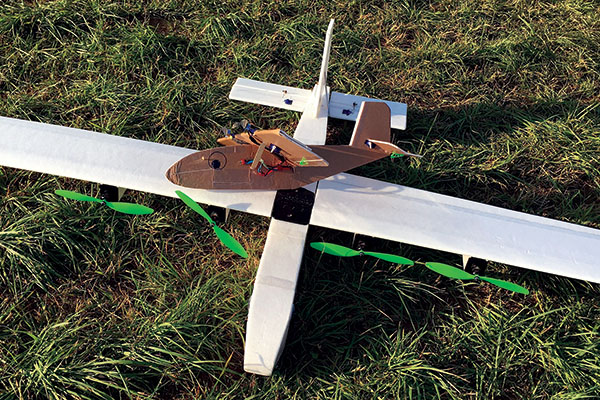
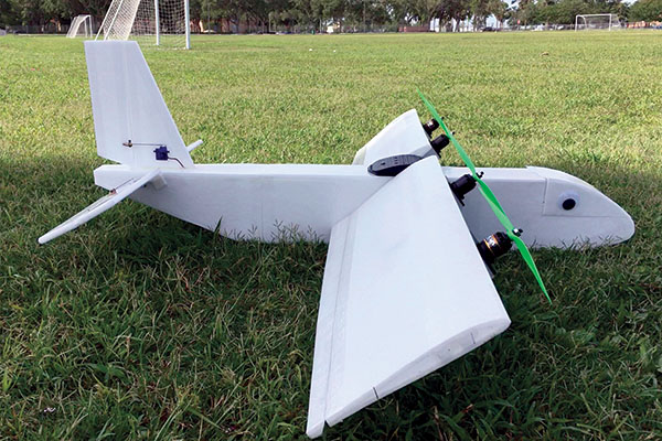
This is a good size comparison between the two models. In this view, the Buster is fitted with an 80-inch wing, so it’s slightly bigger than before.
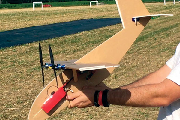
This is a good view of the angle at which the wing was glued onto the fuselage of the baby Buster. The photo was taken before its maiden flight.
Taking the airplane out on its first test flight, I had everything mounted with zero incidence angles so that I could get a feel for the airplane on its first couple of flights. With the wing mounted at a zero incidence angle, the fuselage was noticeably pitched up a few degrees as it flew through level flight. I brought the airplane down and adjusted the wing incidence angle to approximately 2°. When I got the aircraft back up into the air, the fuselage was level with the horizon. It was so exciting to see these principles that I’ve learned in class actually work in the real world—not that I had any doubts! After I landed, it was time for the big test. I set the incidence angle to approximately 30°. This would mean that while the airplane flew, the fuselage would be pitched down at such a severe angle that anyone watching it would think that it was about to crash. I spooled up the four motors, testing the thrust against the weight of the aircraft. Holding the wing parallel with the ground, I pushed the airplane into the air and it swiftly pitched up, looped, and slammed into the ground. In my haste to set up Buster’s wing, I forgot to move the battery forward because the fuselage would have been shortened a lot by the new angle. The CG (center of gravity) was way too far back, making the airplane unstable. That night, I fixed Buster and I brought it back out to the field the next morning. I set the wing to a less-absurd angle of approximately 15° (still much higher than any other airplane that I know of) and I had a friend help me hand-launch the airplane so that I could keep my finger on the elevator stick. This time (with the CG in the right spot), Buster got up into the air, but definitely did not like to fly anymore. The airplane was bucking back and forth as the fuselage tried to become level with the oncoming air and then the wing stalled because it was at too high of an angle of attack. I wasn’t even able to get the airplane to turn before it would tip stall and I would have to recover. In the end, I learned that the fuselage creates so much drag at higher angles of attack that the airplane cannot fly unless the fuselage is also at least close to being in the same flightline as the wing. Although this wasn’t a failure, it was a little bit disappointing. I left the idea there and got ready to set Buster up for another experiment. Later in July 2017, while I was at Flite Fest (flitefest.com) in Malvern, Ohio, I spent some time in one of the build tents fabricating a miniaturized version of Buster with a profile fuselage (to eliminate the drag that plagued the realistic Buster). I vaguely knew what I was trying to build, eyeballing the proportions, and I sketched out fuselage shapes directly onto the foam. I was limited in my parts. I only had right-hand propellers for my twin motors, and the smallest battery I had was a 2,200 mAh three-cell LiPo, which made this little 28-inch wingspan airplane weigh more than 1 pound. Everyone was skeptical of the airplane’s airworthiness, especially with the wing “on crooked,” as many people informed me during its impromptu construction. But I made my way to the flightline and had a friend toss it into the air. Honestly, we were expecting it to nose into the ground because of the absurd wing loading and get a few laughs in while it flew briefly in its comical configuration. I gave it full power, threw it wings level (not fuselage level) to the horizon, and I put in some up-elevator, anticipating the drop. This was the best-flying airplane that I brought to the event! The baby Buster was a little touchy to begin with, but after a few flights and some trim, it was incredibly stable—and fast. Several people came by, wondering what kind of an airplane it was. One person even said, “It hurts my brain to watch your airplane fly.”
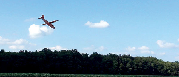
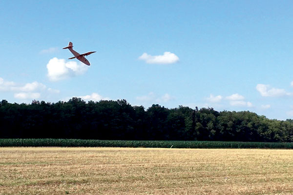
This airplane was fast and very easy to fly! When all trimmed out, the fuselage acted like a big vertical stabilizer.
Explaining the concept of wing incidence angles to curious bystanders was a great experience. Perhaps I inspired them to try something different. If it wasn’t for a couple of brownouts with the receiver, I would still be flying the baby Buster today. Even so, the process of testing these ideas is incredibly fun, and I can’t wait to do more!
This was how the wing and elevator were mounted for the Buster’s final incidence angle test. It was also the configuration during the crash.
Article:


Comments
Tim (not verified)
Incidence on flying wings
Thu, 04/26/2018 - 14:43I fly a lot of wings. I cant get my mind around how to apply incidence. The only thing I can think of is the thrust angle but that could not possible work because the wing would generate so much drag.
Chad Veich (not verified)
Incidence angles
Thu, 04/26/2018 - 14:52I would be interested in the results of experiments with varying incidence angles on the wing while leaving the horizontal stab at a fixed angle, or at least at something other than the same angle as the wing. As long as the wing and stab are set to 0-0 (in relation to each other) the only thing effected is the angle at which the fuselage flies. Correct? What happens when the wing and stab are NOT set to 0-0 in relation to one another?
paul (not verified)
Wow!!! @ 81 years young I
Thu, 04/26/2018 - 15:30Wow!!! @ 81 years young I still Learn something new every day.
Bill Roberts (not verified)
Incident angle
Thu, 04/26/2018 - 15:33Thanks for being bold and making planes that do not follow the conventional type of plane wing/tail construction. You give inspiration and encouragement to think outside of the box when designing and building planes. Thanks.
John Armstrong (not verified)
great article Lucas!!!!
Thu, 04/26/2018 - 15:46Great story. And proud that you are in the same RC club as me.
I'll congratulate again when I see you at the field.
Steve (not verified)
Solving Flight Anomolies
Thu, 04/26/2018 - 16:09Lucas, thanks for sharing your experimental findings!
Seventy years ago I frequented “Clover Hill” to watch the aeromodelers of that era trim their rubber-band-powered, stick-and-tissue, free-flight airplanes. I recall how the “aces” looked forward to helping a novice trim-out a “tough-dog;” an airplane with some hard-to-solve flight anomalies.
Your experiments, and my experiences show that sometimes a model airplane will fly while being way off the design specs, and other times not.
If I learned anything from watching those free-flighters back in the 1940s it was to proceed slowly. Test, make small changes and test again.
Another thing I learned: you don't need an engineering degree to make a model airplane fly. Patience and common sense rule!
Steve
Mike (not verified)
Incidence
Thu, 04/26/2018 - 16:38Another plus is the horizontal and vertical stabs are out of the way of the main wing for smoother airflow and better control! Same reason the put a horizontal stab on the top of the vertical stab on many planes.
Roy Glenn, AMA 27066 (not verified)
Center of gravity
Thu, 04/26/2018 - 16:53When the wing was positioned at 30°, the center of gravity should not have changed significantly. While the nose was shorter, so was the tail. With the first model having a full fuselage, the air moving against it would force the aircraft to pitch up.
Jim Petro (not verified)
anything can fly .......except when it counts
Thu, 04/26/2018 - 17:52Embry-Riddle was still in Miami in 1959 and we had a very small graduating class. Nothing like today existed but our era put man in space and on the moon. When our club has occasions hosting kids, I bring the bag of "anything can fly" parts of cheap store bought balsa gliders. With simple mods, I demonstrate the glider airplane ....then turn it backwards and it flys as a canard.......but the eye-opener is when the horizontal stabilizer it removed and it is a flying wing.
Next I bring out a few sheets of paper.....remember the 'Planet of the Apes' when Heston folds a glider ?..........and show throwing the sheet...the wadded ball....and the folded glider.
What I would really like to do is to throw their smartphones and show those don't fly.....but now they have time to work with their hands without interruptions.
Jim
Bill Krummel (not verified)
Incidence of wings
Thu, 04/26/2018 - 18:31You failed to mention that you must increase the incidence of the horizontal stab approximately the same as the wing. If you don't and the wing flies at 0 degrees, the stab will act as one big up elevator and the airplane will be impossible to fly. Built a Sea Fury that had too much positive incidence on the wing with zero incidence in the stab. Take off was almost a disaster, plane pitched up immediately, had to fly with 1/2 stick down elevator to get her home, not enough down trim to compensate so much positive lift in the wing. That's why most Corsairs fly a little tail high, because of the positive incidence of the wing
Dave Finkleman (not verified)
Incidence
Thu, 04/26/2018 - 19:47Sorry about this, but the article is naive and even wrong in some respects. The incidence of an airfoil is the angle between the mean chord line and the relative wind. The incidence for all configurations in the article is zero! Wings stall at incidence more than a few degrees. If the aircraft flies at all, the “incidence” could not be 15 degrees, let alone thirty degrees. Everything observed is caused by the fuselage alone. Although the publication is not a scholarly discourse, I advise that you have such submissions reviewed by someone with relevant background.
Beerbatter (not verified)
Wrong
Wed, 12/19/2018 - 17:37You made a pretty good attempt at criticizing his write up, but you are the one that is totally wrong. The angle of the wing cord relative to the wind you are referring to is called the Angle of Attack. The incidence is in fact the angle between the wing cord and the longitudinal reference axis of the fuselage. Maybe it is you who should have his comments reviewed by someone with more knowledge of the subject than yourself before posting.
Brian Jones (not verified)
Awesome Project!
Thu, 04/26/2018 - 20:53Flite Fest 2017! It was great to be there in the build tent with you on this project. The baby buster flights were a riot. I'm glad that you were able to write up the experience and get it published!
JOE NANINI (not verified)
VC-22 Osprey
Fri, 04/27/2018 - 03:39It looks to me that you are a short hop to making Buster into one
Joe Niedermayr (not verified)
Incidence Angles
Fri, 04/27/2018 - 13:06The important consideration here is not the incident angle of the wing to the fuselage but the incident angle of the wing relative to the control surfaces. Let’s assume we have a symmetrical airfoil wing and a symmetrical airfoil control surface, - (could be stabilizer/elevator or canard surfaces or in the case of a wing only craft the swipe-back wing tips) - all at zero angle relative to each other, - (I.e. zero incident) - moving horizontally in the zero angle direction through the air. That setup would produce no lift and only drag. To be able to fly it needs lift to offset the weight of this object. A positive incident angle of the wing provides this lift and the control surface is producing that incident with up elevator. The fuselage angle relative to the flight path or the wing / control surface determines only how much drag is created by the fuselage. What can be confusing with lifting airfoils like the CLARK-Y for example, - is, - if they are installed sitting flat on their lower flat surface, - they actually already have a positive incident. This is because their zero lift actually accrues at a front down angle.
Dean (not verified)
Incidence Angles
Fri, 04/27/2018 - 20:34Great article - it really filled in the blanks for me as I continue to be exposed to the fine points of flying. My question pertains to the relationship of incidence angles between the wind and the elevator. I've talked to many guys at the field, especially glider aficionados and they tend to play with the elevator incidence, typically +1 or 2 degrees for stability and better float. Any comments on this would be most appreciated. I've tried it, it works, but I'd like to know why. Thanks
Steve K (not verified)
Incidence angle experiment article
Sat, 04/28/2018 - 21:38Lucas
The angle of incidence is the angle of the wing chord line relative to a reference line in the fuselage. The reference line is not necessarily the center line of the fuselage. Suppose the fuselage is circular in the side view. There are an infinite number of center lines. In reality there are 3 major lines to consider: 1. The chord line of the wing, 2. the chord line of the horizontal stabilizer, 3. the thrust line. In your profile Buster all 3 of those lines appear to be essentially parallel. This is a very common arrangement in R/C aircraft. the fact that those lines are arranged at approximately 30 degrees to the fuselage center line is almost irrelevant because the profile fuselage offers little drag influence in the direction of flight as it is essentially a 2-d shape similar to the circular fuselage mentioned above. In the more complicated case where the fuselage is a 3-d shape its attitude and thus its center of drag in the direction of flight becomes more relevant. If you had your motors mounted on Busters fuselage and their thrust vector along the fuselage center line, the mathematical analysis gets far more complicated. With that sort of arrangement the experimental approach would have been much more interesting and I suspect you would be doing a lot of repairs to buster before you got a controllable flight.
Steve
Scott (not verified)
Incidence angles
Sun, 04/29/2018 - 23:59Being a person supposedly schooled in aerodynamics, I am surprised that he did not once mention decalage, or the angle betweein the stab and the wing. He knows about it, as you can see from his wing and stab setups. I would presume the decalage stayed about the same as he played with the wing incidence. So he is setting up the airplane to fly, but changing the angle of the fuselage. What he is really playing with is fuselage drag. Dumb test.
charlie (not verified)
please dont criticize him
Wed, 01/29/2020 - 16:41he is in fact playing with incidence angles, he just had a side problem of fuselage drag
Nicky Wyeth (not verified)
wing incidence
Tue, 05/01/2018 - 09:06know very well about wing incidences,as i flew free flight, before radio control in the 1960's.Great to read an article on stabilizer tilt !
Milt Woodham (not verified)
incidence angle
Thu, 05/10/2018 - 19:18Incidence angle is the difference in wing and horizontal stab angles of attack, and is not the difference between wing and fuselage center lines. At least this is what I've always been taught by aeronautics experts.
But a doggoned interesting experiment.
Milt Woodham
Colorado Springs, CO
Charlie (not verified)
incidence angles and science fair
Wed, 01/29/2020 - 16:37I am doing a science fair on this and just found this article it is useful, but I wonder what would happen if you had the motor level with the fuselage, could it possibly fly with the fuselage level and direct the air downwards because of the wing angle i would love to see and participate in this experiment if you decide to do it please email me at [email protected] I would love to see this type of aircraft become a real GA (general aviation) ultralite or something
Charles Murray (not verified)
Wing and horizontal stabilizer
Sun, 01/24/2021 - 16:38After reading the comments above submitted by individuals in the modeling community; I remain confused concerning these angular inputs to the design. I would think that a horizontal line through the fuselage from nose to tail, (floor reference plane) as X = 0, Y = 0, Z = 0). This would be the reference line that every thing was constructed to.
Motor 3 degrees negative from 'Z' = zero, from 'X' = 0, plus 3 degrees
Wing 6 degrees positive from Z = 0
and last but not least the horizontal stabilizer. located at coordinates such as: at X = ?, Y ? and Z?
If anyone has a solution as to where the Horizontal Stabilizer belongs I would be happy to hear.
Add comment