Written by Rhoe Apt Homebuilt biplane makes a great sport model Product Review As seen in the Spring 2018 issue of Park Pilot.
Specifications:
Type: Semiscale sport Wingspan: 36 inches Wing area: 364.5 square inches Length: 29.25 inches Weight: 17.75 ounces Power system: 2208-17 Suppo motor; GWS 9 x 5 propeller; 12-amp ESC; 3S 800 mAh LiPo batteryDownload free plans
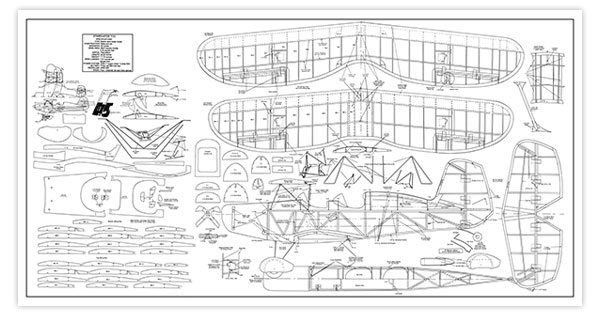 Click here for full-size plans (61" x 32" JPG)
Click here for tiled plans (24 8.5" x 11" JPG files in zip format)
Bonus Videos
Product Review
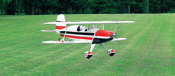
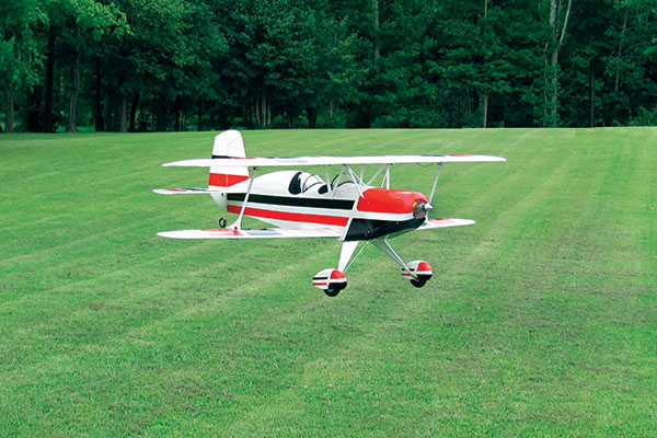
In the early 1950s, Lou Stolp designed the original full-scale Starduster. This was the first in a long line of beautiful, elliptical-wing biplanes conceived for homebuilders who wanted a beautiful airplane above all else. Its second seat and additional power made this airplane the most popular in the Stolp line. This model is a 11/2-inch-to-the-foot semiscale version of the SA300 Starduster Too. When Lou designed the Starduster Too, he threw away his straightedge. This aircraft has a hard-to-cover headrest, so I used the top outline and made a turtledeck instead. The fuselage is narrower to help eliminate drag. I put the same sweep in the bottom wing as in the top wing for less chance of a tip stall when it is flying. When you sweep the wing, the root has to stall first. After much coaxing, the tip will stall. I have wanted to build this airplane for more than 5 years. If you decide to build one, you will be rewarded with a beautiful airplane that flies as well as it looks.Laminating the Outlines
Start with laminating all of the outlines because of the drying time. I made forms in the shape of the inner curve of the laminated outlines. (The stabilizer and elevator are two pieces and the fin and rudder are three pieces.) The forms are made from 1/2-inch plywood scrap and the wing form is made from 3/4-inch plywood scrap. I cut them to shape and sealed the edges. I ironed scrap covering onto the edges where the glued laminations will go and used 3D finishing nails, 1 inch apart, on both sides of the forms. I cut five pieces of 3/4 x 1/16 x 48-inch medium balsa for wing outlines and three pieces of 1/2 x 1/16 x 36-inch balsa for the stabilizer and elevator, and fin and rudder. I used a 11/2-inch plastic PVC drainpipe capped on both ends to soak the balsa for 24 hours. Narrow strips cut from a 1-gallon round nylon bottle keep the rubber bands from sticking to the balsa on the outside. Titebond (titebond.com) wood glue was thinned with enough water so that it would easily brush on. The glue was applied to the strips with a brush then I added the nylon strips and form around molds, lacing over the nails (similar to lacing your shoes), with 1/16-inch rubber bands tight enough to form the laminations. I let this dry for 24 hours, removed it from the molds, took off the outer plastic, and relaced it to dry another 48 hours. You can’t build the wings until all of the laminations are dry.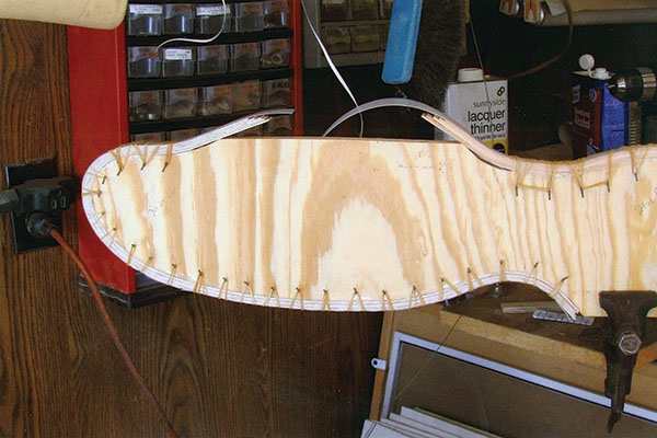
The form for the wing laminations was made from 3/4-inch plywood, with finishing nails and rubber bands holding everything together.
Fuselage
Build the stabilizer/elevators then the fin/rudder. Build the fuselage frames using 1/8-inch square basswood for the side outline. Using medium balsa for the uprights and diagonals, add the 1/32-inch plywood doublers to the inside of F-12. The diagonals hold the bottom’s pretty curve. More importantly, they hold the top longeron straight. Everything is positioned by the top longeron. Join the sides with medium balsa crossbraces, starting at the tail and working forward with the frame upside down. Install the 1/8-inch sheet to the frame behind F-1 and install the firewall. I capstripped the top longeron with 1/8-inch square balsa and feathered it to a point at F-8. At the rear cabane mount, cut out the 1/8-inch capstrip and add a 1/8-inch square piece of 1-inch basswood. Add the formers from F-1 to F-8. Now bend the cabane struts according to the drawings on the plans. Bend the front two angles first then lay your wire on the side view with the bends you just made at a 90° angle from the table, and bend the rest of the strut. Using yellow spade clips for #10 gauge wire and blue clips for #12 gauge wire, I drilled 7/64-inch holes in the clips for wing mounting with 4-40 x 1/4 socket-head cap screws. Take the plastic off of all of the clips and separate the large one to go over the two 1/16-inch cabane struts (front) then solder the clips. The larger one goes on the front over both wires, and the smaller one on the rear. Drill the basswood crossbrace at F-1 and mount the cabane struts. Lace the cabane struts to the crossbrace with 10-pound nylon fishing line. Temporarily lace the rear of the cabanes to the top longeron and bend the clips to fit the bottom of the wing. Make sure the clips are parallel to the top longerons and shim the front if necessary. Adjust the back ones if necessary by remelting the solder. To mount the stabilizer, place the fuselage upright on the building board. Ensure that the top longerons are parallel to the building board. If not, shim under the fuselage. Mount the stabilizer by lining it up with the centerline of the fuselage, making sure it is parallel with the building board. Now mount the fin and align it with the fuselage centerline and the stabilizer and cut the rear cabane ties. They will later be mounted outside of the 1/64-inch plywood. I fitted and glued the 1/64-inch plywood wrap at the front and between the cockpits then I used another piece to strengthen the splice. The lower stringers were installed. A 1/32-inch shim on the top stringer between the 1/8-inch sheet doubler and F-6 made it blend better. The lower one is not shimmed. Next I added the wing saddle doubler F-13 and the 3/32 x 3/8-inch balsa above the stabilizer at the fuselage. I then added the top keel F-16. Add the 1/16-inch sheet wrap on F-5 and F-6 then capstrip the top of the keel F-16 with 1/16 x 3/16 balsa and install the 3/32-square basswood turtledeck stringers. Capstrip the stringers with 1/16 x 3/32 balsa feathered to a point at F-8. You will also need to capstrip the top longeron from the 1/64 plywood wrap and feather it to F-7. Glue a 1/8-inch square piece of balsa 1/4 inch long where the rear cabane struts will go.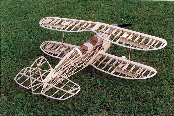
The form for the wing laminations was made from 3/4-inch plywood, with finishing nails and rubber bands holding everything together. The completed fuselage, shown here before covering, helps illustrate the construction methods used on the aircraft.
Building the Wings
I cut the laminated outlines lengthwise using my 9-inch band saw, marking the inside with a pen and sanding the cut smooth.
Begin the wings by pinning the LE (leading edge) and laminated outline to the building board. Next, pin the bottom 3/32 basswood spar bottoms in place and add the appropriate ribs. I glued this together with the 1/16 sheet aileron hinge plates (with the aileron LEs at 45°), and then add the top rear 3/32 basswood spar tops. They should be lower than the tops of the ribs.
Glue the 3/32 sheet front webs between all of the ribs. When it is dry, remove the assembly from the plans. Now you can razor plane and sand the top of the wings to shape. The wings are similar, except for the outline shapes. The top wing has no dihedral; the bottom wing has 3/4-inch dihedral per panel.
Glue the top wing rear spar to 1/8-inch basswood between the spars in the center with epoxy. On the lower wing, I cut the wing and blocked one tip 11/2 inches for dihedral. I glued 1/8-inch square basswood with epoxy between rear spars. Glue the LE, TE (trailing edge), and front spar.
Mount the top wing before you sheet the top wing’s LE with soft 1/32 balsa. Then sheet the bottom wing’s LE. At the aileron hinge line and aileron LE line, I used 1/64-inch plywood. With 1/16-square balsa, I capstripped all of the wing ribs and added an additional 1/16 x 3/16 piece of balsa to stiffen BR-7 and TR-6.
Carefully sand the tops of the ribs. I used Titebond and epoxy to build the airplane. After this is done, cut the ailerons free from the wings.
Mounting the Wings
The stabilizer should be set at 0° incidence. Place the top wing upside down on the building board. With the fin touching the centerline of the fuselage and the cabane struts inverted, place the fuselage on the top of the wing. Drill four 3/32 holes in TW-14 and TW-15 to mount the top wing.
Don’t tap TW-14 and TW-15, but screw the wing to the cabane struts then drill and install 4-40 blind nuts. Now fit the bottom wing to the wing saddle trim and sand it to align it with the top wing.
I used a 4-40 x 11/4 screw through two scrap plywood pieces to hold the bottom wing in position so that I could drill through F-9 and the LE and into the spar web with a 1/8-inch drill bit. Now install the 1/8-inch dowel. Drill the TE and F-11 with a 5/32 drill and install the blind nut to mount the bottom wing then sheet the 1/32 LE on the top wing.
Landing Gear
I made the front and back landing gear with .062 music wire and a .025 music wire center brace. I mounted the landing gear to the landing gear blocks F-14 and F-15. I used a #2 servo screw to mount it in each corner. I used .010 copper wire (obtained from multistrand 12-gauge wire) to wrap the front and back of the landing gear together in a figure eight pattern then I soldered it.
Wrap and solder the .025 center brace on the wheel end. Loop a small rubber band over the front landing gear and the .025 wire brace. Tighten then wrap it around the landing gear to get a good stretch to the small S hook on the rear landing gear wire, providing a shock absorber.
Cowl and Motor Mount
The cowl is made as per Milton Dickey’s “Cheap & Cheerful Cowls & Canopies” article in Flying Models (June 2004; flying-models.com). If you don’t have that article, the process isn’t complicated.
I used two 2 x 6 pine scraps cut 6 inches long and glued them together to make a blank to form the cowl. After they were glued together, I used my jointer to narrow it to the width required. I taped the side pattern to the block and cut out the side view.
I used my 3/4-inch round-over bit in the router to round the top edges and the angle grinder to finish the plug. Screw two 3/8 x 2.5-inch lag bolts into the back so that you can hold it in the vise. Cut the bottom off of a clear, two-liter soda bottle. With your heat gun, start shrinking the bottle at the back, keeping the spout in the front middle until it is tight on the plug and has no wrinkles.
When it is as you like it, cut the rear off and drill a 1/8-inch hole in the cap. Using an air gun, blow it off the plug. Now cut the hole for the motor and it is finished.
The motor mount and motor are mounted inside of the cowl with four #2 screws. The motor should have 2° to 3° of right thrust. I used no downthrust.
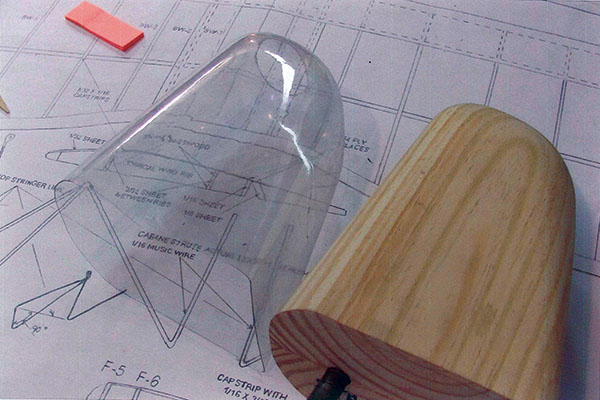
A plug is used to make the cowl.
Radio Installation
I mounted the servos as shown on the plans. The aileron servos are held in place with a piece of Scotch tape. The pushrods are made from .035 welding wire. The rudder and elevator pushrods are bushed at F-5 and F-7 and the pushrod exits the aileron. The pushrods are retained with a straight pin as shown on the plans.
The elevator and rudder pushrods are held in position by the pushrod springs. The battery box is positioned in front of the instrument panel and the receiver is rubber banded to F-11.
Covering
I covered the airplane with white 21st Century MicroLite film (coverite.hobbico.com), except for the landing gear spats and under the center section of the lower wing. The red and black, the white on the lower wing, spats, and cowl stripe are TowerKote covering material (towerhobbies.com).
When ironing the TowerKote on the cowl, be careful not to get it too hot or the cowl will deform. I used the plug to trim the cowl, keeping the heat as low as possible.
Wheels and Wheel Pants
The wheels are made with four pieces of 3/32 x 21/2 square balsa, laminated at 90° to each other, and two pieces of 1/32 plywood, 3/4 square for each wheel. Drill a 3/16-inch hole and tap with a 1/4-20 tap. I used a 1/4-20 bolt to turn the wheels at 2,400 rpm, using a nut and washer on each side.
After the wheels were turned, I drilled a nylon wing bolt with a 3/32 bit to press in the K & S Precision Metals (ksmetals.com) brass tube for the axle bearing. The tail wheel is made the same way from 1/4-inch birch plywood. For the tail wheel, a nylon wing bolt is drilled to make a 1/16-inch hole. The wheels were coated with two coats of clear PVC cement and sanded smooth.
I painted the hubs with silver and when they were dry, I brushed on black flat paint.
Glue the wheel pants together and drill a straight, 1/16-inch hole. I used a 1/4-inch round-over bit in the router to shape it then sand it to a good finish.
Check the center of gravity and all of the surface directions and throws and you should be ready for your first flight.
Flying
The first flight was uneventful. I took off from a paved surface and landed in a wheat field. The airplane handled well. I shortened the elevator throw, and on the second flight I did some loops. I found that it doesn’t like inverted flight.
Even with the wheel pants, the model will take off from and land on grass. It has sufficient power and is becoming more pleasurable to fly as I become accustomed to its characteristics.
The Starduster Too is solid in the air, with no bad characteristics. If you decide to build this model, you will enjoy its beautiful looks, and it flies well.

Free plans available at www.theparkpilot.org
Article:


Comments
Michael Ramsey (not verified)
Elegant
Thu, 06/21/2018 - 15:12What a pretty biplane! I can see the lamination technique becoming a popular building method of light and strong airframe elements, once a modeler builds this airplane for the first time. I'm glad that you demonstrated the cowl molding process, but I'd personally want to make it out of balsa so that the whole airplane can be finished in matching covering. Can't wait to see your next project.
Tom (not verified)
Laser cut short kit?
Thu, 09/13/2018 - 17:16Do you know if anybody cuts a short kit for this model?
[email protected] (not verified)
Starduster
Fri, 02/28/2020 - 12:21Does anyone have full layout printed plans? If so how can I get them?
JCO (not verified)
Vector File
Tue, 04/27/2021 - 07:22Is there a Vector file version of this plan available?
It would make a sharper print
rachelleh
Vector file
Tue, 04/27/2021 - 12:06Hello. I'm sorry but our authors do not provide us with vector files for plans.
JCO (not verified)
Vector File
Wed, 04/28/2021 - 05:08Thanks for letting me know, I'll get the JPG printed which will be fine.
rachelleh
Vector file
Mon, 06/07/2021 - 12:32You're welcome! Happy building!
Add comment