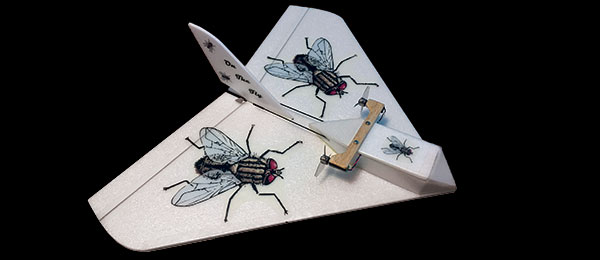
Written by Tim Bailiff Delta wing soars with recycled parts Construction As seen in the Winter 2019 issue of Park Pilot.
Download free plans
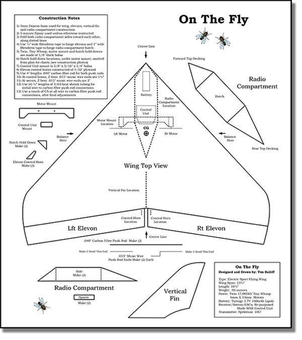 Click here for full-size plans (23.01" x 15.64")
Click here for tiled plans 8.5" x 11"
Specifications:
Type: Foam RC Wingspan: 13.5 inches Weight: .95 ouncesMaterial List:
- 14 x 16-inch sheet of 3 mm Depron foam
- 8-inch piece of .040-inch carbon-fiber rod
- 8-inch piece of .015-inch music wire
- 2-inch piece of 3/64-inch heat-shrink tubing
- 1 x 1-inch piece of 1/32-inch plywood
- 5/8 x 5/16 x 1/4-inch balsa block
- 3 x 2 x 1/8-inch balsa sheet
- 1-inch wide roll Blenderm medical tape
- 2-inch wide roll Scotch clear packing tape
- (2) #0 x 1/4-inch pan-head screws
- (2) 5/16-inch servo screws
- Thin CA glue with accelerator
- 5-minute epoxy
- (2) 6 x 15 mm 17,300 Kv Special Sauce coreless motors
- (2) 31 mm three-blade Rakon Heli propellers
- Turnigy 3.7-volt 160 mAh LiPo battery
- Blade mSR five-in-one control unit
To keep the parts count low, I decided to build a simple flying wing. The wing design I chose is called a “cropped delta.” It is basically a triangular wing with the tips removed. By cropping the tips, undesirable tip stalls are effectively avoided. I have had success with this design in the past and I found that regardless of size, the aerodynamic principles remain consistent. I chose to use 3 mm Depron. I figured a flat foam wing couldn’t get any simpler. I used 6 x 15 mm, 17,300 Kv brushed motors. They are actually hop-up ducted-fan motors used to power the popular Tiny Whoop quadcopters. Using the recommended three-blade ducted-fan propellers, but not the shrouds, effectively converted the motors and propellers into ductless fans. At 17,300 rpm, two of these little screamers provide the On The Fly with plenty of get up and go! Having a 13.5-inch wingspan and an all-up flying weight of .95 ounces, this little delta wing is fast and maneuverable. Don’t let its ability to fly fast intimidate you. It can also slow down and fly very nicely. In fact, throughout its entire flight envelope, it remains stable and pleasantly manageable. It’s predictable and fun! I suggest using the electronics that I chose. If you have something different you’d prefer to use, please be my guest. In fact, if you’d care to substitute anything along the way, go for it; however, keep in mind the CG (center of gravity), which is 37/8 inches from the nose. Remember, model aircraft that are built lighter, fly better. You might have much of what is required in the materials list. If you do need to purchase anything, I recommend you visit your local hobby retailer first before looking elsewhere. In these rough economic times, your patronage will surely be appreciated. Should you not find what you need locally, the internet is always an excellent resource.
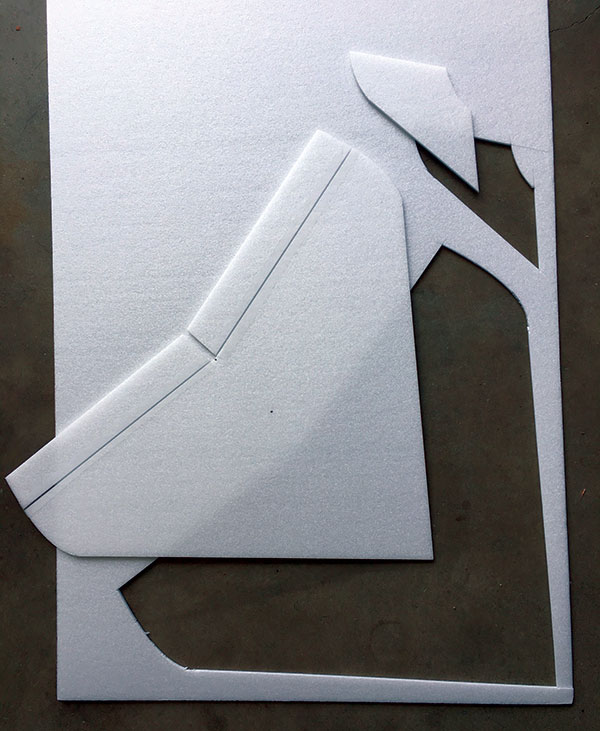
The wing, elevons, and vertical fin are cut from 3 mm Depron.
I already had many of the smaller items on the list, but I purchased the 3 mm Depron from my local hobby shop. The two motors and counter-rotating, three-blade propellers were purchased from Tiny Whoop (tinywhoop.com). I chose the Special Sauce motors and paired them with Rakon Heli smoke-colored propellers. The 3.7-volt 160 mAh LiPo battery was purchased from HobbyKing (hobbyking.com). The five-in-one control unit I used was harvested from a loved, but worn-out, Blade MSR helicopter. New or used control units can be found online. Construction: You will need a full-size copy of the plans/template sheet. It can be downloaded from the Park Pilot website then copied to a memory stick or similar storage device. Take your memory stick to an office supply store and have the plans/template sheet printed at full size. The sheet is 16 x 18 inches (portrait orientation). If you purchase two, you can use one for templates while keeping the other in good shape. Begin by using the templates to mark your wing, vertical fin, and radio compartment pieces onto the 3 mm Depron foam sheet. As you cut out all of the pieces, I recommend that you remove the wing and control surfaces (elevons) as a single piece then cut the elevons from it. After doing so, remove some material from the underside LEs (leading edges) of each elevon lengthwise. The underside of the final LEs should angle back roughly 45°. After they are hinged, they can deflect freely into the down position. Now, lay the wing upside down on a flat surface and prepare to place three pieces of 2-inch packaging tape as shown in the construction photos. You should place one short piece at the nose, one longer piece spanwise centered across the CG, and one final long piece near the TE (trailing edge) from wingtip to wingtip. These longer pieces of tape are your spars. Again, refer to the photos for clarity. Also be sure to keep the wing flat as you work. You don’t want to accidently tape a warp into the wing! Turn the wing right side up and hinge each elevon with a 1/2-inch strip of Blenderm tape. Do this along the wing’s entire TE. Leave a slight gap at the hinge lines to facilitate ease of movement. Don’t stretch the Blenderm when applying because it can also create a warp in the wing. Mix up a small batch of 5-minute epoxy and glue the vertical fin in place. The fin location is at the center rear of the wing and is also indicated on the template sheet. As the epoxy sets up, be sure the fin remains vertical and aligned straight along the wing’s centerline. The 1/32-inch plywood control horns are 5/8 inch high and 1/4 inch wide at the base, tapering to 3/16 inch at the top. Sand the top round and then drill a tiny .015-inch hole centered in the rounded top portion of each control horn. Also sand the base of the horns so that they slant forward enough to place the .015 holes at the hinge lines. The horns can now be epoxied into shallow slots cut through the Blenderm tape and into the top of each elevon. As shown in the plans and photos, both slots should be placed 1/4 inch from the vertical fin. Make sure the control horns remain aligned and vertical as they dry. Begin by deeply scoring each of the two Depron compartment sides, as indicated on the plans. They should be on the insides mirroring each other. Now epoxy the two 11/4-inch Depron spacers in place. The front spacer should be slightly behind the front score lines and the rear spacer should be slightly ahead of the rear score lines. These spacers separate the two sides at the bottom of the compartment. The rear spacer is placed on the edge and will be trimmed as necessary when fitting the control unit into place. Carefully join the front and rear of the radio compartment with a touch of epoxy. Be sure to keep both sides aligned and vertical as the glue sets. Next, epoxy the front and rear top decking in place. They are slightly oversized. Carefully align and then trim for a neat fit. Also ensure that the hatch fits squarely between them. The front of the hatch can now be hinged using a 1-inch piece of Blenderm tape. I recommend that you place a 2-inch length of clear packing tape onto the entire top of the radio compartment. Press it down firmly and then neatly trim the tape flush with the sides of the radio compartment. This adds to the overall strength of the structure. Remember to cut across the tape at the rear of the hatch, slightly ahead of the rear decking.
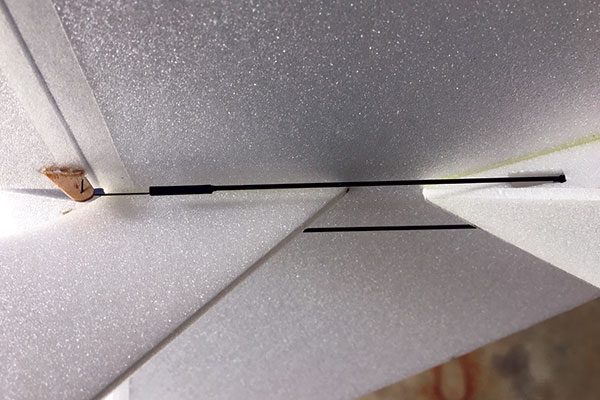
Here you can clearly see the pushrod exits and control horn placement and attachments.
Next, epoxy the radio compartment to the top of the wing, as indicted on the plans. Be sure it is centered and aligned along the centerline of the wing. After the glue has hardened, open the hatch and epoxy the two triangular, 1/8-inch thick balsa hold-downs in place. They should align with the front edge of the rear decking, at the rear corners of the hatch area. Be sure they are flush with the top of the opening so that the hatch can close all of the way. Installing the motors: In this section, the ductless fans will be placed on a mount and then secured to the top rear of the hatch. Cut the 1/8-inch balsa motor mount, as shown on the plans, then sand it smooth and round its edges. Decide which will be the top of the two Tiny Whoop Special Sauce motors and lightly sand that area of the metal motor housings. That will give them some “tooth” for the glue to grab onto. Next, use 5-minute epoxy to glue the tops of the motors to the outboard, underside of the balsa motor mount facing toward the rear. As the glue hardens, ensure that the motors are parallel with each other and pointing straight back. As seen from the rear, the right motor spins clockwise and the left motor spins counterclockwise. Keeping that in mind, install the two counter-rotating, three-blade propellers facing forward. It makes a big difference. Carefully drill two 1/16-inch holes through the balsa motor mount as indicated on the template sheet. Center the motor mount on the top rear of the hatch cover, perpendicular to the centerline. Check that both holes are positioned correctly over the balsa hold-downs, located beneath the foam hatch. While holding the motor mount securely in place, drill two small pilot holes and attach it using the two 5/16-inch servo screws. Take your time and slowly screw through the hatch, into the balsa hold-downs. Don’t overtighten the screws. Snug is sufficient. Now, remove the screws and motor mount, open the hatch and using a pin, place a tiny amount of CA glue down into each of the balsa hold-down screw holes. Use enough CA to wick into the balsa holes, but do not allow any of it to touch the foam. When the CA sets, it will toughen the threaded holes in the balsa, allowing for repeated removal and replacement of the screws. The most unique feature about this little delta wing is the use of a harvested and repurposed Blade mSR (five-in-one) helicopter control unit. It is an amazing piece of micro RC technology and the heart and soul of the On The Fly. It not only has a receiver and two servos, but also two separate ESCs. One simple modification is needed. On the servo side of the control board is a small rectangular metal cover. This houses a gyro that must be disabled. Carefully pry up the little metal cover. Using small needle-nose pliers, carefully pull off the tiny component housed within. Be sure to get it all. The reason for this modification is that the Blade mSR control unit is designed to be mounted vertically. In that position, the gyro does a great job of stabilizing the helicopter. However, with the controller installed in the horizontal position, the gyro causes unwanted inputs to occur during rolls. Next, go into your transmitter programming and choose the delta wing mix. You might also need to reverse a function or two. This would be a good time to power up and bind your receiver to your transmitter. When binding, position your throttle stick to the low position, with your transmitter at least 2 feet away. The control unit will take a few moments to initialize. After a successful bind, remember to center your servos. The control board comes with two mounting holes in it and it will be mounted horizontally. The balsa mounting block is 3/4 x 5/16 x 1/4 inch. With the 1/4-inch side facing up, epoxy the block lengthwise, along the center bottom of the radio compartment. Position it ahead of and touching the rear Depron spacer. Although this is not shown on the plans (for clarity), be sure to check out the photos. Mount the controller using two #0 x 1/4 pan-head screws. Position the control board with the servos facing up and the tapered edges of the board to the rear. Remove the controller and apply a small amount of CA directly into the holes made by the mounting screws. Again, avoid any CA contact with the foam. Next are the pushrods. Follow the photos and template sheet and you’ll have no problems. Start by cutting two 4-inch lengths of .040 carbon-fiber rod. Now cut two 11/4-inch pieces of .015 music wire and two 2-inch pieces of the same wire. Make a small Z-bend in one end of each piece. The Z-bends on the 11/4-inch wires should mirror each other as should the small Z-bends on the 2-inch pieces. On the other end of the 2-inch music wire pieces, make the larger Z-bends using the plans as your guide. Use the construction photos to help clarify. Next, cut four 1/2-inch pieces of 3/64-inch heat-shrink tubing. Connect the straight ends of the Z-bend wires onto both ends of the carbon-fiber rods by heating the tubing. The overlap should be the length of the tubing (1/2 inch) and each carbon-fiber rod should have a short and long piece of Z-bend wire. Again, use the construction photos. As you work, decide which pushrod will be for which elevon and align the small Z-bends accordingly.
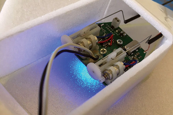
A Blade mSR control unit was used. You can see the pushrod attachments.
Now use the photos to help locate where to cut two pushrod exit holes in the rear sides of the radio compartment. Use the pushrods to help with the alignment. Now it’s time to connect the two motor leads to the motor jack located on the bottom side of the control board (opposite the servos). Because the control board and the motor leads come with female plugs, you will need to do some soldering. There are several ways to connect both motor leads to the single motor jack, but the following is what I chose to do. I had a few short pieces of fine red and black multiconductor wire and a bag of 1.27 mm 2 x 50 male pin, double-row connectors. I simply removed six pins from a connector and bent two pins 90°. I soldered two 1-inch pieces of red wire to one bent pin and two 1-inch pieces of black wire to the other bent pin. To the other four ends of the wires, I soldered one of the remaining four straight pins. I used some heat-shrink tubing to insulate any bare wiring while leaving roughly 1/8 inch of each pin exposed. If using this method, you can now connect the two 90° pins to the jack on the bottom of the control unit. The wires should face the rear. Plug one red pin and one black pin into each motor lead. Should one or both of your motors spin the wrong direction, simply unplug the offending motor lead and reverse the red and black pins. I found it easiest to feed the pushrods through the exits first then connect to the forward holes on the linear servo arms. Do this before the control unit is mounted. After the pushrods are connected, the control board is secured to its mount using two #0 x 1/4 pan-head screws. Your pushrods will likely need some fine-tuning at the servos and as you connect to the elevon control horns. To adjust the length at the control horn, hold the carbon-fiber rod then gently twist the Z-bend music wire until it pops loose from the heat-shrink tubing. This will allow the music wires to twist and slide in and out. They can even be removed to facilitate connecting to the control horns. After the wires are back in position, ensure that the elevons are in the neutral position. Place a tiny amount of CA glue at the heat-shrink tubing where the wires join to the carbon-fiber rod and allow it to wick in.
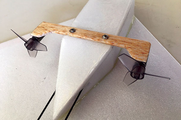
The model uses Tiny Whoop motors with three-blade propellers.
Color and graphics: Now it’s time to add some color and/or graphics to your airplane. I chose to use free clip art that I found online. I simply downloaded it to my computer and made copies in various sizes. I then printed them onto a clear, full-page shipping label. I next sprayed the label with a light coat of Rust-Oleum clear matte finish to seal in the ink and protect it from moisture. It was simple to cut out the graphics, remove the backing, and stick them to my airplane. Setup: When flying outside, my On The Fly frequently gets wet because I fly over grass. If built according to this article, your airplane will weigh less than 1 ounce. That equates to a low “crunch factor” on grass. In other words, grass is your friend! It’s time to turn on your transmitter, install your 160 mAh 3.7-volt LiPo battery, and allow your control unit to initialize. Use a small piece of foam to help secure your battery forward in the nose. Now with your battery in place and your twin ductless fans mounted in place, check that your airplane balances 37/8 inches from the nose. Balancing the aircraft slightly ahead of the recommended CG location is fine, but behind is not. Adjust as needed. Ensure that your motors counter-rotate in the proper direction and check that your elevons move correctly as well. I recommend that you set your lower dual rates at 50% and use them for your first flight. Leave your high rates at whatever you initially have. Flying: Hand launching is the same indoors or out. Using your right hand, gently grasp your delta wing by the right wing’s LE. Apply full power with your left hand and then gently toss your airplane, slightly nose up, using a “Frisbee-like” motion. If you are outside, be sure to launch into the wind. After the airplane is airborne, allow it to gain some airspeed and gently climb. When it is at a comfortable height, slightly reduce the power and trim it for level flight. Now try a few gentle turns. It handles nicely and is easy to fly. As you become more familiar with your On The Fly, try a few rolls. I find they are best performed with full power, starting from a slightly nose-high attitude. You can also perform beautiful loops from level flight.
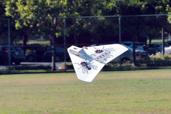
The On The Fly has no bad habits in the air and can be flown indoors or outdoors.
If you want to spice things up, switch to high rates and hold on. Rolls happen in the blink of an eye and pylon turns are super crisp. You will find that your On The Fly can perform any aileron and elevator maneuver you can imagine. Talk about fun! When it’s time to land, simply reduce the throttle or even cut it all together. Your little delta wing should glide very well and you needn’t worry about tip stalls! It slows down nicely and remains controllable at any speed. The aircraft has no bad habits. If required, you can use a little throttle to help carry you in and gently land it at your feet.
Article:


Comments
Mary Ayers (not verified)
build it : on the fly
Sun, 01/20/2019 - 14:03when are the plans available
rachelleh
Free plans
Thu, 01/24/2019 - 16:46Jack (not verified)
Disabling gyro
Wed, 02/20/2019 - 10:56Can you post pictures of the gyro removal from the
5 in 1 board ? It is not clear from The picture of the board in the power box that the gyro is removed.
Doug LeRoy (not verified)
Disable Gyro
Thu, 04/18/2019 - 22:20See this RCGroup thread. When you pop the cover off, there is a wire underneath that you pull off. Leave cover off. https://www.rcgroups.com/forums/showthread.php?1379836-MCX-gyro-disable/...
蕭旭 (not verified)
Build the first one-
Sat, 04/04/2020 - 09:56No experience, but hopefully I can build one for my son.
Add comment